PAGE 17
MARS/CAP Coverage
The AT-897Plus provides continuous tuning coverage over its specified range; not just in the
ham bands. This makes it useful for MARS or CAP operation, or any other legal HF operation.
Operation with a PC / CAT
Although the AT-897Plus uses the transceiver’s CAT port for tuning control, the AT-897Plus
is also designed to allow the user to continue to use the CAT interface with the transceiver for
PC control.
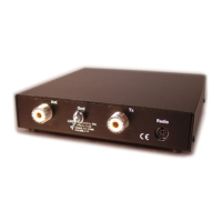
If PC control of the radio is desired, simply hook the PC’s CAT interface cable (such as
Yaesu CT-62) to the Computer jack on the rear of the AT-897Plus.
Any rig control software on the computer must be set to use the 4,800 baud rate, as this is the
communication rate used by the AT-897Plus for controlling the radio.
The AT-897Plus monitors the Computer port for activity before beginning any tuning cycle.
Only when the CAT line is idle for a period of time will the AT-897Plus take over control of the
CAT line in order to perform a tuning cycle. When the tuning cycle is complete, control of the
CAT interface is returned to the PC.
This procedure is completely automatic, and is transparent to the user. Simply hook up a PC,
and use the rig control software as normal. Press the TUNE button on the AT-897Plus when
tuning is desired.
THEORY OF OPERATION
Some basic ideas about impedance
The theory underlying antennas and transmission lines is fairly complex, and in fact employs
a mathematical notation called “complex numbers” that have “real” and “imaginary” parts. It is
beyond the scope of this manual to present a tutorial on this subject
2
, but a little background will
help in understanding what the AT-897Plus is doing, and how it does it.
In simple DC circuits, the wire resists current flow, converting some of it into heat. The
relationship between voltage, current, and resistance is described by the elegant and well-known
“Ohm’s Law”, named for Georg Simon Ohm of Germany, who first discovered the principle in
1826. In RF circuits, an analogous but more complicated relationship exists.
RF circuits also resist the flow of electricity. However, the presence of capacitive and
inductive elements causes the voltage to lead or lag the current, respectively. In RF circuits, this
resistance to the flow of electricity is called “impedance”, and can include all three elements:
resistive, capacitive, and inductive.
2
For a very complete treatment of this subject, see any edition of the ARRL Handbook for Radio Communications
(previously the Handbook For Radio Amateurs).