PAGE 8
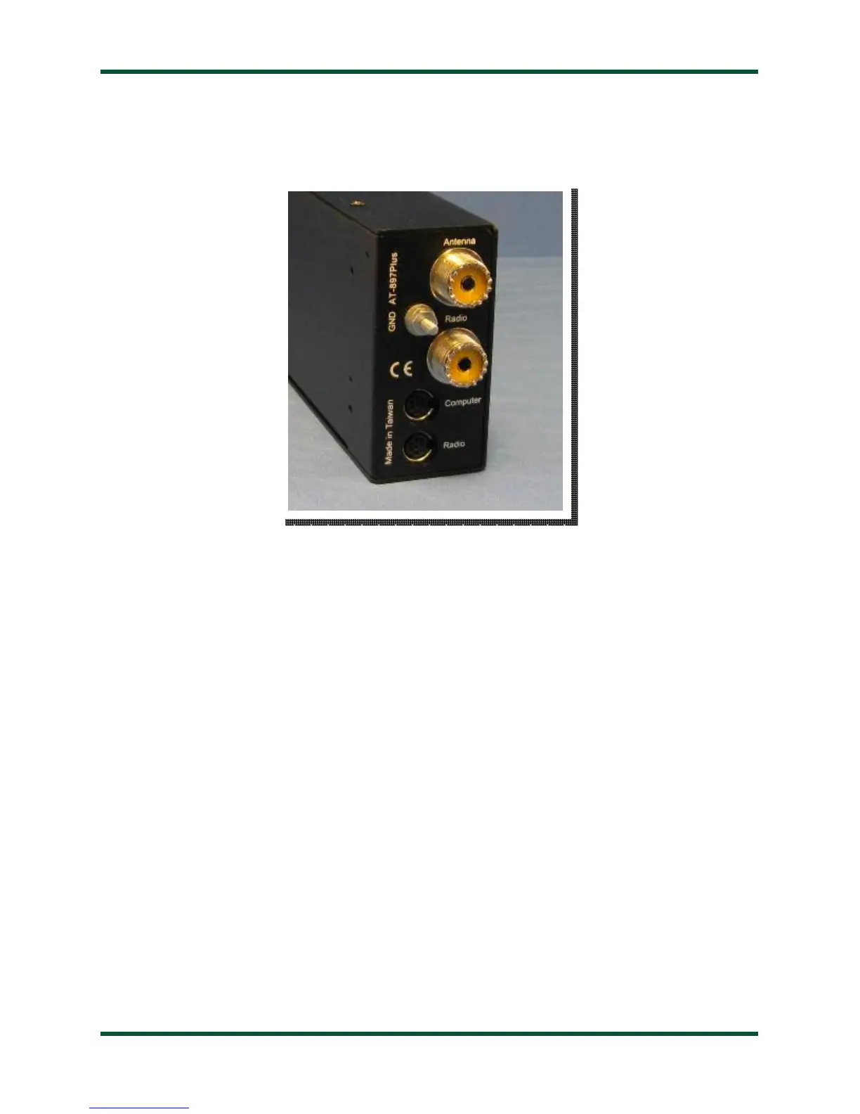
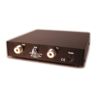
Rear Panel
The rear panel of the AT-897Plus features five connectors.
•
Antenna connector: Connect the 50-ohm coax antenna feedline to this standard SO-239
connector.
•
GND connector (nut): Connect to station ground.
•
Radio connector: Connect the 50-ohm coax jumper cable from this standard SO-239
connector to the ANT jack on the back of the transceiver.
•
Computer connector: This 8-pin mini-DIN connector connects to a personal computer via
Yaesu’s CT-62 cable or similar computer-to-CAT interface cable. Use of this port is optional;
it is provided for those hams who would like to control their FT-897 via computer. This is a
pass-thru port to the CAT Out port, and is switched under software control by the AT-
897Plus’s microprocessor. The firmware of the AT-897Plus has been written such that this will
seem transparent to the user -- if using CAT to control your FT-897, just plug the PC’s CAT
cable into this port instead of the CAT jack on the back of the transceiver.
•
Radio connector: This 8-pin mini-DIN connector is for connection to the FT-897’s
CAT/LINEAR jack. The AT-897Plus controls the PTT, power level, and operating mode via
CAT commands sent to the transceiver. The AT-897Plus also reads the operating frequency
directly from the transceiver so that it knows where to store tuning memory data.