3
G6A Low Signal Relay
G
6
A
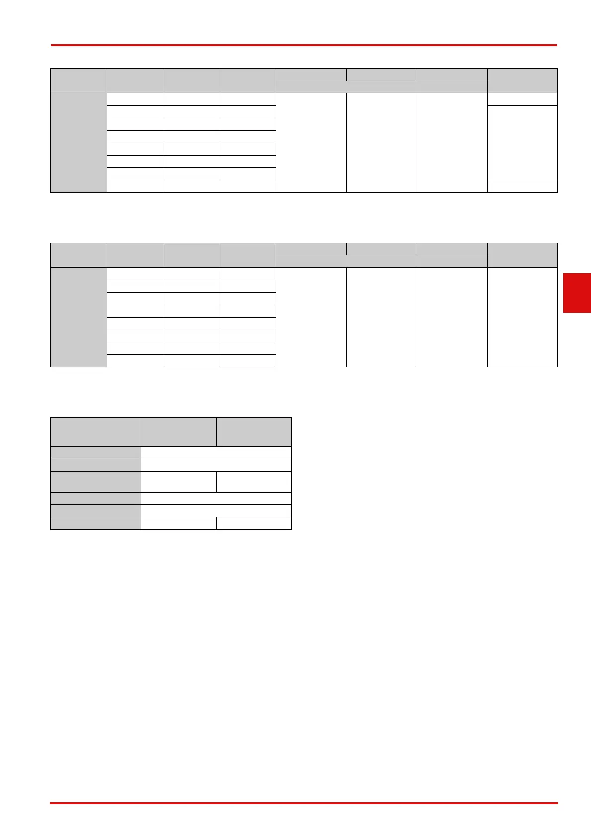
●Coil: Double-winding Latching (Standard Models)
Note1. The rated current and coil resistance are measured at a coil temperature of 23°C with a tolerance of ±10%.
2. Operating characteristics are measured at a coil temperature of 23°C.
3. The maximum voltage is the highest voltage that can be imposed on the relay coil.
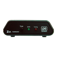
●Coil: Double-winding Latching (Low-sensitivity Models)
Note1. The rated current and coil resistance are measured at a coil temperature of 23°C with a tolerance of ±10%.
2. Operating characteristics are measured at a coil temperature of 23°C.
3. The maximum voltage is the highest voltage that can be imposed on the relay coil.
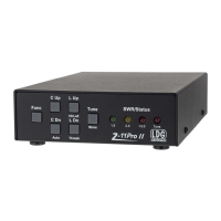
●Contacts
Contact form Rated voltage
Rated current
(mA)
Coil resistance
(Ω)
Set voltage (V) Reset voltage (V) Max. voltage (V)
Power consumption
(mW)
% of rated voltage
DPDT (2c)
3 VDC 66.7 45
70% max. 70% max.
200%
(at 23°C)
Approx. 200
4.5 VDC 40.2 112
Approx. 180
5 VDC 36 139
6 VDC 30 200
9 VDC 20 450
12 VDC 15 800
24 VDC 7.5 3,200
48 VDC 4.2 11,520 Approx. 200
Contact form Rated voltage
Rated current
(mA)
Coil resistance
(Ω)
Set voltage (V) Reset voltage (V) Max. voltage (V)
Power consumption
(mW)
% of rated voltage
DPDT (2c)
3 VDC 120 25
70% max. 70% max.
150%
(at 23°C)
Approx. 360
4.5 VDC 79.9 56.3
5 VDC 72.5 69
6 VDC 60 100
9 VDC 40 225
12 VDC 30 400
24 VDC 15 1,600
48 VDC 7.5 6,400
Load
Item
Resistive load
Inductive load
Contact type Bifurcated crossbar
Contact material Ag (Au-Alloy) contact
Rated load
0.5 A at 125 VAC;
2 A at 30 VDC
0.3 A at 125 VAC;
1 A at 30 VDC
Rated carry current 3 A
Max. switching voltage 250 VAC, 220 VDC
Max. switching current 2 A 1 A