5
G6A Low Signal Relay
G
6
A
■Engineering Data
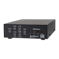
Note: “Maximum voltage” is the maximum
voltage that can be applied to the Relay
coil.
Test Conditions: Shock is applied in ±X, ±Y, and ±Z directions three times each with and without energizing the Relays to check the
number of contact malfunctions.
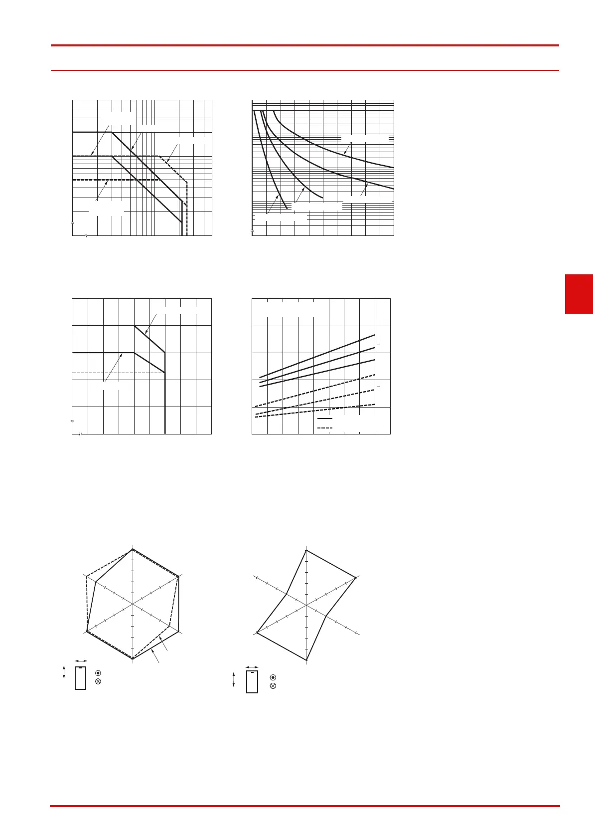
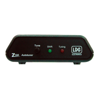
●Maximum Switching Power ●Durability
●Ambient Temperature vs. Maximum
Coil Voltage
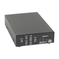
●Ambient Temperature vs. Must
Operate or Must Release Voltage
●Shock Malfunction
G6A-274P G6AK-274P
AC inductive
(cosφ = 0.4)
DC resistive
AC resistive
Switching current (A)
Switching voltage (V)
5.0
2.0
1.0
0.5
0.2
0
20 50 100 200 500
DC inductive
(L/R = 7 ms)
Durability (x104 operations)
Switching current (A)
0 0.2 0.4 0.6 0.8 1.0 1.2 1.4 1.6 1.8 2.0
10,000
5,000
3,000
1,000
500
300
100
50
30
10
5
3
125 VAC, resistive
125 VAC, inductive
30 VDC, inductive
30 VDC, resistive
Maximum coil voltage (%)
Ambient temperature (°C)
250
200
150
100
50
0
‑40 20 30 40 50 60 70 80 90 100
100, 150, 200 mW
360, 400 mW
110
100
80
60
40
20
0
-60 -40 -20 0 20 40 60 80 100 120
Ambient temperature (°C)
On the basis of rated voltage (%)
Sample: G6A-274P
Number of Relays: 10 pcs
max.
min.
max.
min.
Must operate voltage
Must release voltage
X
X
Z'
Z
Z
Z'
Shock direction
Unit: m/s
2
Y
Y
Y'
Y'
X
X
X'
X'
1,000
1,000
1,000 1,000
200
400
600
800
800
600
400
200
1,000
1,000
De-energized
Energized
Sample: G6A-274P 5 VDC
Number of Relays: 10 pcs
Z'
Z
Z
Z'
Shock direction
Unit: m/s
2
Y
Y
Y'
Y'
X
X
X'
X'
1,000
1,000
1,000 1,000
200
400
600
800
800
600
400
200
1,000
1,000
Sample: G6AK-274P 5 VDC
Number of Relays: 10 pcs