DM442 Digital Stepping Drive Manual V1.0
Tel: +000 0000-00000000 2
2. Specifications
Electrical Specifications (T
j
= 25℃/77℉)
Parameters
Min Typical Max Unit
Output current 0.5 - 4.2 (3.0 RMS) A
Supply voltage +20 +36 +40 VDC
Logic signal current 7 10 16 mA
Pulse input frequency 0 - 200 kHz
Isolation resistance 500 MΩ
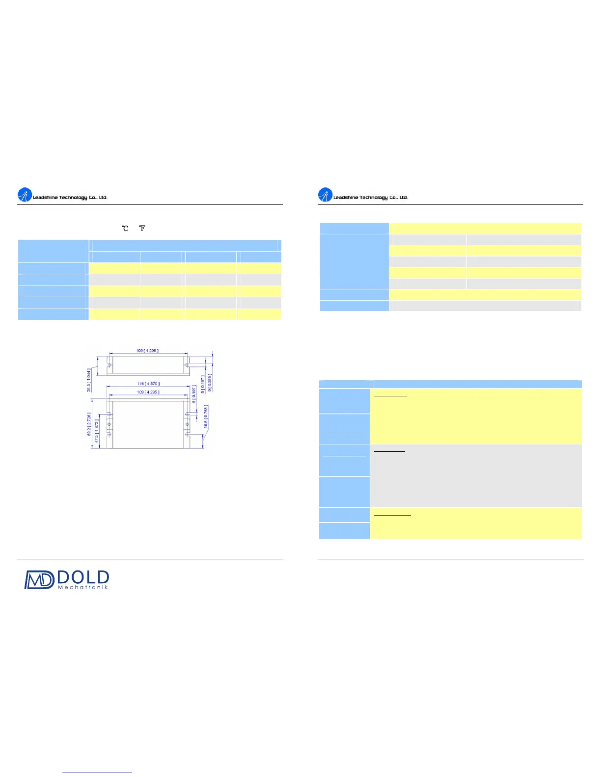
Mechanical Specifications (unit: mm [inch])
Figure 1: Mechanical specifications
Elimination of Heat
Drive’s reliable working temperature should be <70℃(158℉), and motor working temperature
should be <80℃(176℉);
It is recommended to use automatic idle-current mode, namely current automatically reduce to
60% when motor stops, so as to reduce drive heating and motor heating;
It is recommended to mount the drive vertically to maximize heat sink area. Use forced cooling
method to coo
l the system if necessary.
DM442 Digital Stepping Drive Manual V1.0
Tel: +000 0000-00000000 3
Operating Environment and other Specifications
Cooling Natural Cooling or Forced cooling
Environment
Avoid dust, oil fog and corrosive gases
Vibration
5.9m/s
2
Max
Storage Temperature -20 ℃ - 65℃ (-4℉ - 149℉)
Weight Approx. 200g (7.05oz)
3. Pin Assignment and Description
The DM442 has two connectors, connector P1 for control signals connections, and connector P2 for
power and motor connections. The following tables are brief descriptions of the two connectors.
More detailed descriptions of the pins and related issues are presented in section 4, 5, 9.
Connector P1 Configurations
Pin Function Details
PUL+
PUL-
Pulse signal: In single pulse (pulse/direction) mode, this input represents pulse
signal, each rising or falling edge active (software configurable); 4-5V when
PUL-HIGH, 0-0.5V when PUL-LOW. In double pulse mode (pulse/pulse) ,
this input represents clockwise (CW) pulse,active both at high level and low
level (software configurable). For reliable response, pulse width should be
longer than 2.5μs. Series connect resistors for current-limiting when +12V or
+24V used. The same as DIR and ENA signals.
DIR+
DIR-
DIR signal: In single-pulse mode, this signal has low/high voltage levels,
representing two directions of motor rotation; in double-pulse mode (software
configurable), this signal is counter-clock (CCW) pulse,active both at high
level and low level (software configurable). For reliable motion response, DIR
signal should be ahead of PUL signal by 5μs at least. 4-5V when DIR-HIGH,
0-0.5V when DIR-LOW. Please note that rotation direction is also related to
motor-drive wiring match. Exchanging the connection of two wires for a coil
to the drive will reverse motion direction.
ENA+
ENA-
Enable signal: This signal is used for enabling/disabling the drive. High level
(NPN control signal, PNP and Differential control signals are on the contrary,
namely Low level for enabling.) for enabling the drive and low level for
disabling the drive. Usually left UNCONNECTED (ENABLED).