DM442 Digital Stepping Drive Manual V1.0
Tel: +000 0000-00000000 8
Multiple Drives
It is recommended to have multiple drives to share one power supply to reduce cost, if the supply has
enough capacity. To avoid cross interference, DO NOT daisy-chain the power supply input pins of
the drives. Instead, please connect them to power supply separately.
Selecting Supply Voltage
The power MOSFETS inside the DM442 can actually operate within +20 ~ +40VDC, including
power input fluctuation and back EMF voltage ge
nerated by motor coils during motor shaft
deceleration. Higher supply voltage can increase motor torque at higher speeds, thus helpful for
avoiding losing steps. However, higher voltage may cause bigger motor vibration at lower speed, and
it may also cause over-voltage protection or even drive damage. Therefore, it is suggested to choose
only sufficiently high supply voltage for intended applications, and it is suggested t
o use power
supplies with theoretical output voltage of +20 ~ +36VDC, leaving room for power fluctuation and
back-EMF.
7. Selecting Microstep Resolution and Drive Output Current
Microstep resolutions and output current are programmable, the former can be set from full-step to
102,400 steps/rev and the latter can be set from 0.5A to 4.2A. See more information about Microstep
and Output Current Setting in Section 13.
However, when it’s n
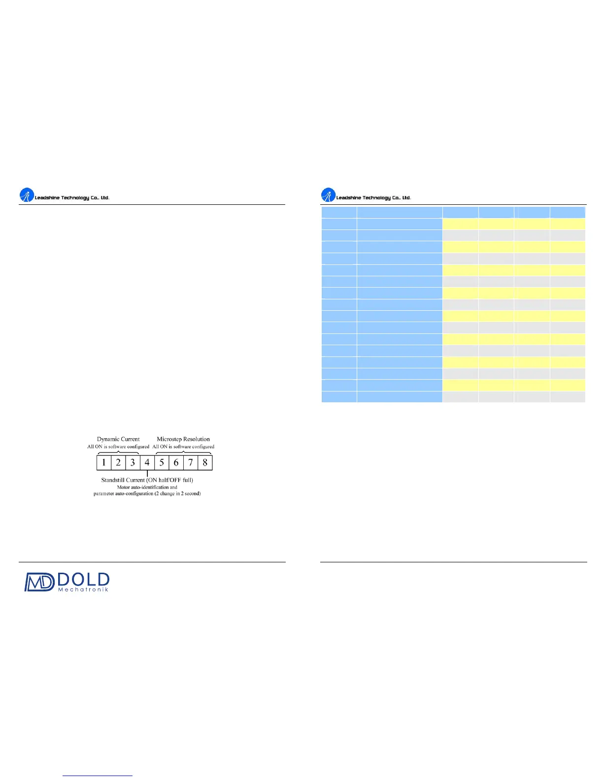
ot in software configured mode, this drive uses an 8-bit DIP switch to set
microstep resolution, and motor operating current, as shown below:
Microstep Resolution Selection
When it’s not in software configured mode, microstep resolution is set by SW5, 6, 7, 8 of the DIP
switch as shown in the following table:
DM442 Digital Stepping Drive Manual V1.0
Tel: +000 0000-00000000 9
Microstep
ON ON ON ON
2 400
OFF ON ON ON
4 800
ON OFF ON ON
8 1600
OFF OFF ON ON
16 3200
ON ON OFF ON
32 6400
OFF ON OFF ON
64 12800
ON OFF OFF ON
128 25600
OFF OFF OFF ON
5 1000
ON ON ON OFF
10 2000
OFF ON ON OFF
20 4000
ON OFF ON OFF
25 5000
OFF OFF ON OFF
40 8000
ON ON OFF OFF
50 10000
OFF ON OFF OFF
100 20000
ON OFF OFF OFF
125 25000
OFF OFF OFF OFF
Current Settings
For a given motor, higher drive current will make the motor to output more torque, but at the same
time causes more heating in the motor and drive. Therefore, output current is generally set to be such
that the motor will not overheat for long time operation. Since parallel and serial connections of
motor coils will significantly change resulting inductance and resistance, it is therefore important to
se
t drive output current depending on motor phase current, motor leads and connection methods.
Phase current rating supplied by motor manufacturer is important in selecting drive current, however
the selection also depends on leads and connections.
When it’s not in software configured mode, the first three bits (SW1, 2, 3) of the DIP switch are used
to set the dynamic current. Select a setting closest to your motor’s required
current.