DM442 Digital Stepping Drive Manual V1.0
Tel: +000 0000-00000000 10
Dynamic current setting
Peak Current RMS Current SW1 SW2 SW3
Default/Software configured (0.5 to 4.2A) ON ON ON
1.46A 1.04A
OFF ON ON
1.91A 1.36A
ON OFF ON
2.37A 1.69A
OFF OFF ON
2.84A 2.03A
ON ON OFF
3.31A 2.36A
OFF ON OFF
3.76A 2.69A
ON OFF OFF
4.20A 3.00A
OFF OFF OFF
Notes: Due to motor inductance, the actual current in the coil may be smaller than the dynamic
current setting, particularly under high speed condition.
Standstill current setting
SW4 is used for this purpose. OFF meaning that the standstill current is software configured, and ON
meaning that standstill current is set to be the same as the selected dynamic current.
By default, the current automatically reduced to 60% of the selected
dynamic current two second
after the last pulse. Theoretically, this will reduce motor heating to 36% (due to P=I
2
*R) of the
original value. Reduction rate and idle time can be configured in the PC software ProTuner. See
more information in section 13.
8. Wiring Notes
In order to improve anti-interference performance of the drive, it is recommended to use twisted
pair shield cable.
To prevent noise incurred in PUL/DIR s
ignal, pulse/direction signal wires and motor wires
should not be tied up together. It is better to separate them by at least 10 cm, otherwise the
disturbing signals generated by motor will easily disturb pulse direction signals, causing motor
position error, system instability and other failures.
If a power supply serves several drives, separately connecting the drives is recommended
instead of daisy-chaining.
It
is prohibited to pull and plug connector P2 while the drive is powered ON, because there is
DM442 Digital Stepping Drive Manual V1.0
Tel: +000 0000-00000000 11
high current flowing through motor coils (even when motor is at standstill). Pulling or plugging
connector P2 with power on will cause extremely high back-EMF voltage surge, which may
damage the drive.
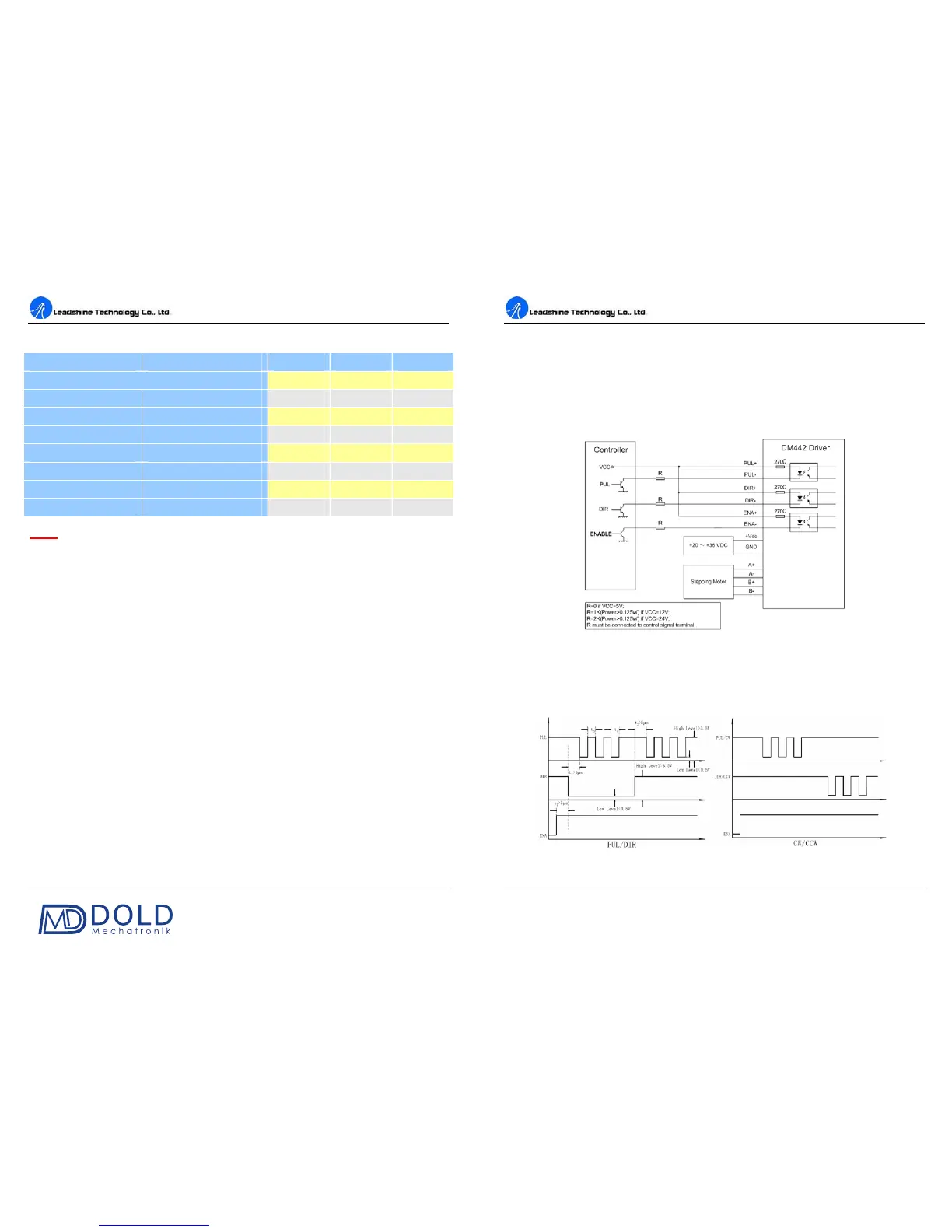
9. Typical Connection
A complete stepping system should include stepping motor, stepping drive, power supply and
controller (pulse generator). A typical connection is shown as figure 9.
Figure 9: Typical connection
10. Sequence Chart of Control Signals
In order to avoid some fault operations and deviations, PUL, DIR and ENA should abide by some
rules, shown as following diagram:
Figure 10: Sequence chart of control signals