DM442 Digital Stepping Drive Manual V1.0
Tel: +000 0000-00000000 6
setting the drive output current multiply the specified per phase (or unipolar) current rating by 1.4 to
determine the peak output current.
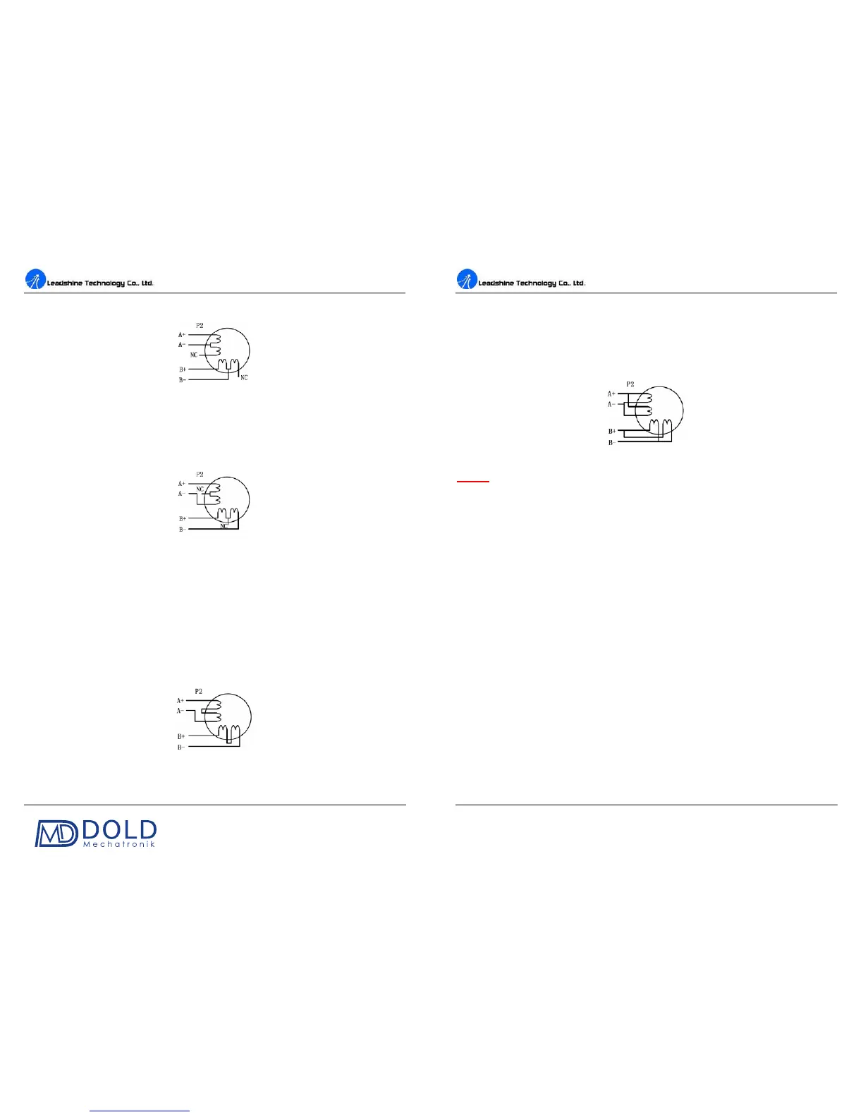
Figure 5: 6-lead motor half coil (higher speed) connections
Full Coil Configurations
The full coil configuration on a six lead motor should be used in applications where higher torque at
lower speeds is desired. This configuration is also referred to as full copper. In full coil mode, the
motors should be run at only 70% of their rated current to prevent over heating.
Figure 6: 6-lead motor full coil (higher torque) connections
Connections to 8-lead Motors
8 lead motors offer a high degree of flexibility to the system designer in that they may be connected
in series or parallel, thus satisfying a wide range of applications.
Series Connections
A series motor configuration would typically be used in applications where a higher torque at lower
speeds is required. Because this configuration has th
e most inductance, the performance will start to
degrade at higher speeds. In series mode, the motors should also be run at only 70% of their rated
current to prevent over heating.
Figure 7: 8-lead motor series connections
DM442 Digital Stepping Drive Manual V1.0
Tel: +000 0000-00000000 7
Parallel Connections
An 8 lead motor in a parallel configuration offers a more stable, but lower torque at lower speeds. But
because of the lower inductance, there will be higher torque at higher speeds. Multiply the per phase
(or unipolar) current rating by 1.96, or the bipolar current rating by 1.4, to determine the peak output
current.
Figure 8: 8-lead motor parallel connections
NEVER disconnect or connect the motor while the power source is energized.
6. Power Supply Selection
The DM442 can match medium and small size stepping motors (from NEMA frame size 14 to 34)
made by Leadshine or other motor manufactures around the world. To achieve good driving
performances, it is important to select supply voltage and output current properly. Generally speaking,
supply voltage determines the high speed performanc
e of the motor, while output current determines
the output torque of the driven motor (particularly at lower speed). Higher supply voltage will allow
higher motor speed to be achieved, at the price of more noise and heating. If the motion speed
requirement is low, it’s better to use lower supply voltage to decrease noise, heating and improve
reliability.
Regulated or Unregulated Power Supply
Both regulated and unregulated power supplies can be used to supply the drive. However,
unregulated power supplies are preferred due to their ability to withstand current surge. If regulated
power supplies (such as most switching supplies.) are indeed used, it is important to have large
current output rating to avoid problems like current clamp, for example using 4A supply for 3A
motor-drive operation. On the other hand, if unregulated supply i
s used, one may use a power supply
of lower current rating than that of motor (typically 50%~70% of motor current). The reason is that
the drive draws current from the power supply capacitor of the unregulated supply only during the
ON duration of the PWM cycle, but not during the OFF duration. Therefore, the average current
withdrawn from power supply is considerably less than motor current. For example, two 3A motors
can be well supplied by one power supply of 4A rating.