DM442 Digital Stepping Drive Manual V1.0
Tel: +000 0000-00000000 4
Selecting Active Pulse Edge and Control Signal Mode
The DM442 supports PUL/DIR and CW/CCW modes and pulse actives at rising or falling edge. See
more information about these settings in Section 13. Default setting is PUL/DIR mode and rising
edge active (NPN, and PNP control signal is on the contrary).
Connector P2 Configurations
Pin Function Details
+Vdc Power supply, 20~40 VDC, Including voltage fluctuation and EMF voltage.
GND Power Ground.
A+, A- Motor Phase A
B+, B- Motor Phase B
4. Control Signal Connector (P1) Interface
The DM442 can accept differential and single-ended inputs (including open-collector and PNP
output). The DM442 has 3 optically isolated logic inputs which are located on connector P1 to accept
line drive control signals. These inputs are isolated to minimize or eliminate electrical noises coupled
onto the drive control signals. Recommend use line drive control signals to increase noise
immunity
of the drive in interference environments. In the following figures, connections to open-collector and
PNP signals are illustrated.
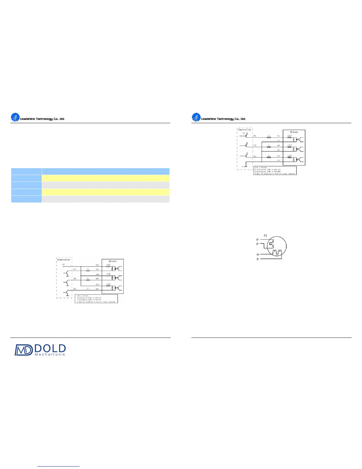
Figure 2: Connections to open-collector signal (common-anode)
DM442 Digital Stepping Drive Manual V1.0
Tel: +000 0000-00000000 5
Figure 3: Connection to PNP signal (common-cathode)
5. Connecting the Motor
The DM442 can drive any 2-phase and 4-phase hybrid stepping motors.
Connections to 4-lead Motors
4 lead motors are the least flexible but easiest to wire. Speed and torque will depend on winding
inductance. In setting the drive output current, multiply the specified phase current by 1.4 to
determine the peak output current.
Figure 4: 4-lead Motor Connections
Connections to 6-lead Motors
Like 8 lead stepping motors, 6 lead motors have two configurations available for high speed or high
torque operation. The higher speed configuration, or half coil, is so described because it uses one half
of the motor’s inductor windings. The higher torque configuration, or full coil, uses the full windings
of the phases.
Half Coil Configurations
As previously stated, t
he half coil configuration uses 50% of the motor phase windings. This gives
lower inductance, hence, lower torque output. Like the parallel connection of 8 lead motor, the torque
output will be more stable at higher speeds. This configuration is also referred to as half chopper. In