DM442 Digital Stepping Drive Manual V1.0
Tel: +000 0000-00000000 12
Remark:
a) t1: ENA must be ahead of DIR by at least 5µs. Usually, ENA+ and ENA- are NC (not
connected). See “Connector P1 Configurations” for more information.
b) t2: DIR must be ahead of PUL active edge by 5µs to ensure correct direction;
c) t3: Pulse width not less than 2.5µs;
d) t4: Low level width not less than 2.5µs.
11. Protection Functions
To improve reliability, the drive incorporates some built-in protection functions. The DM442 uses
one RED LED to indicate what protection has been activated. The periodic time of RED is 5 s
(seconds), and how many times the RED turns on indicates what protection has been activated.
Because only one protection can be displayed by RED LED, so the drive will decide what error to
display according to their priorities. See the following Protection Indications table for displaying
priorities.
Over-current Protection
Over-curre
nt protection will be activated when continuous current exceeds the limit or in case of
short circuit between motor coils or between motor coil and ground, and RED LED will turn on once
within each periodic time (5 s).
Over-voltage Protection
When power supply voltage exceeds 50±1 VDC, protection will be activated and RED LED will
turn on twice within each periodic time (5 s).
Phase Error Protection
Motor power lines wrong & not
connected will activate this protection. RED LED will turn on four
times within each periodic time (5 s).
Attention:
When above protections are active, the motor shaft will be free or the LED will blink.
Reset the drive by repowering it to make it function properly after removing above problems. Since
there is no protection against power leads (﹢,﹣) reversal, it is critical to make sure that power
supply leads correctly connected to drive. Otherwise, the drive will be damaged instantly.
DM442 Digital Stepping Drive Manual V1.0
Tel: +000 0000-00000000 13
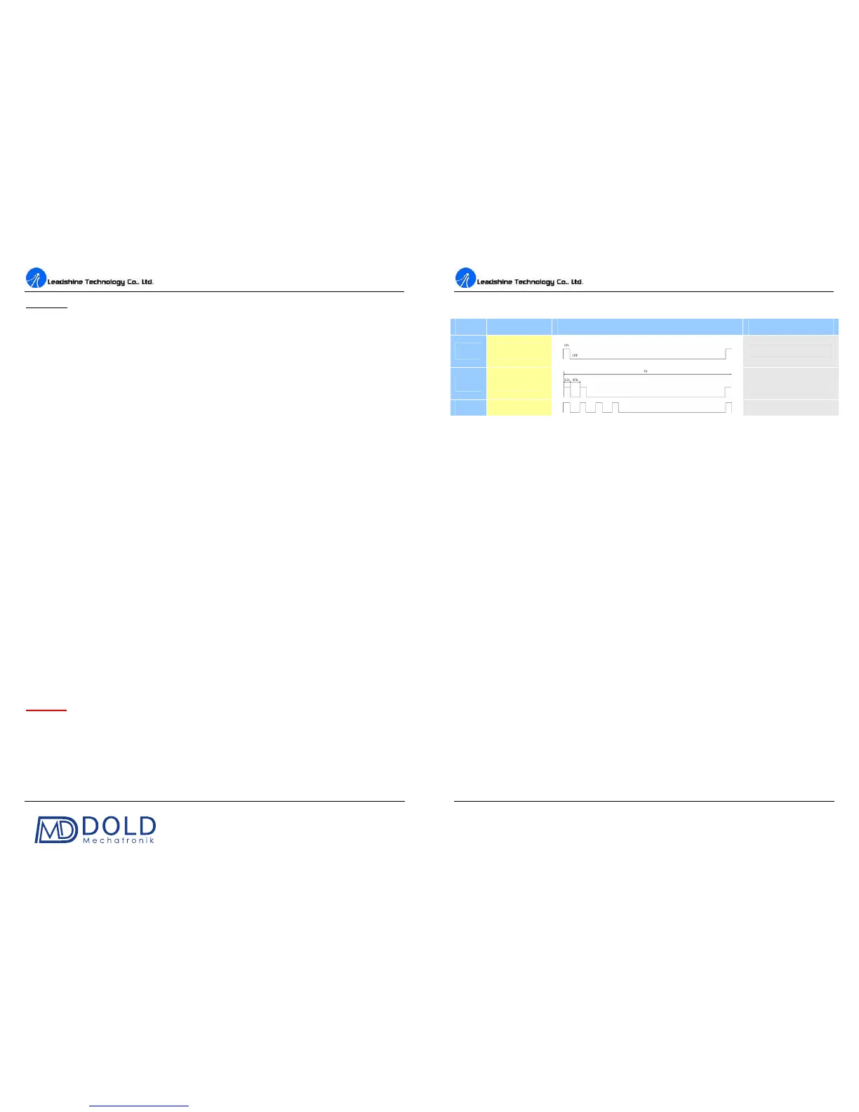
Protection Indications
Priority
Time(s) of ON Sequence wave of RED LED Description
1
st
1
Over-current protection
2
nd
2
Over-voltage protection
3
rd
4
Phase error protection
12. Frequently Asked Questions
In the event that your drive doesn’t operate properly, the first step is to identify whether the problem
is electrical or mechanical in nature. The next step is to isolate the system component that is causing
the problem. As part of this process you may have to disconnect the individual components that make
up your system and verify that they operate independently. It is important to document
each step in
the troubleshooting process. You may need this documentation to refer back to at a later date, and
these details will greatly assist our Technical Support staff in determining the problem should you
need assistance.
Many of the problems that affect motion control systems can be traced to electrical noise, controller
software errors, or mistake in wiring.