18
ENGLISH
C) – Installation
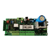
1) Unscrew the screws of the cover and lift the cover. Check that the electronic unit is in good order. In case of doubt do not install the unit and
ask for the intervention of qualified personnel. The container’s accessories (screws, round seal, cable glands) must not be left within the reach
of children since they are a potential danger.
2) Check that the electronic unit is properly fixed to its box. If not, tighten all screws or provide the missing screws.
3) Place the unit near the gate so that the system connection wires’ length is reduced to the minimum.
Caution: For the unit’s correct operation the wires connected to it must not be longer than 10 metres.
4) For increased weather protection we recommend to place the unit under a roof or, even better, in an enclosure having two side walls.
Wherever possible, it is advisable to install the unit at a minimum 1,5 mt level above the ground to keep it out of the reach of children.
5) Before proceeding to assembly place the container so that the side fitted with the cable glands is directed towards the ground.
Caution: Do not assemble the container on wood surfaces.
6) Lift the mobile portion of the connector and proceed to connect the unit wires as described in the following chapters.
Caution : The motors, battery and blinker connection wires must have a 2,5 mm
² minimum size.
D) - Operation
1) Definitions of Controls
Start
Input connected to a push-button placed outside the unit. It is employed to request the gate’s opening or closure (for both wings). This input is usually
connected to a key push-button.
2) Definitions of Safety devices
Photo-cell
Input connected to an optical barrier. It detects and signal the passage of persons or vehicles in the area crossed by the gate or in the nearby area.
3) Definitions of Outputs
Blinker
Lamp’s on/off control. The lamp functions as a warning and optical signaller of potential danger for the gate’s motion.
Motor 1
Output for the opening/closure control of the motor which drives the first gate wing during the closing phase.
Motor 2 (to be used in installations of gates with single wing)
Output for the opening/closure control of the motor which drives the gate wing delayed during the closing phase.
4) Definitions of Power Supply Inputs/Outputs
AC IN (FS1 - FS2)
12Vac or 20Vac input for the electronic board power supply.
OUT 12Vdc (clamps 7 and 8 on terminal board J1)
Power supply output for the photo-cell and/or any other accessory devices.