26
ENGLISH
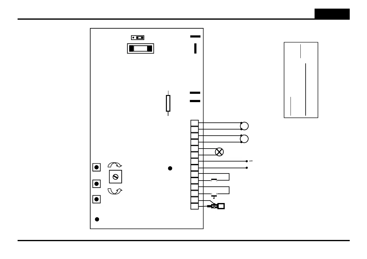
General diagram
CTR57
DL1 - Led
programming
RV1 - Slow-down
speed
P1
Programming
keys
P2 P3
Jumper JP1
Battery charger
3 2 1
BLINKER
AERIAL
1 2 3 4 5 6 7 8 9 10 11 12 13 14
J1
PHOTOCELL
START
M1
M2
MOTOR 2
MOTOR 1
AC IN
Transformer
Battery
connection
Service fuse
F2 0,5A
F1
Battery fuse
F1 10A
COMMON
COMMON
DL2 - Led
photocell
Attention: with the gate positioned
at the half of run, the first
command after a power off always
determines an opening. if not,
reverse the connection of the
motor’s terminals (11-14 on J1).
+
OUT
12 Vdc
—
FS2
FS1
FS4
FS3
+
—
+
+
-