5-18 Performance Verification Rev. D
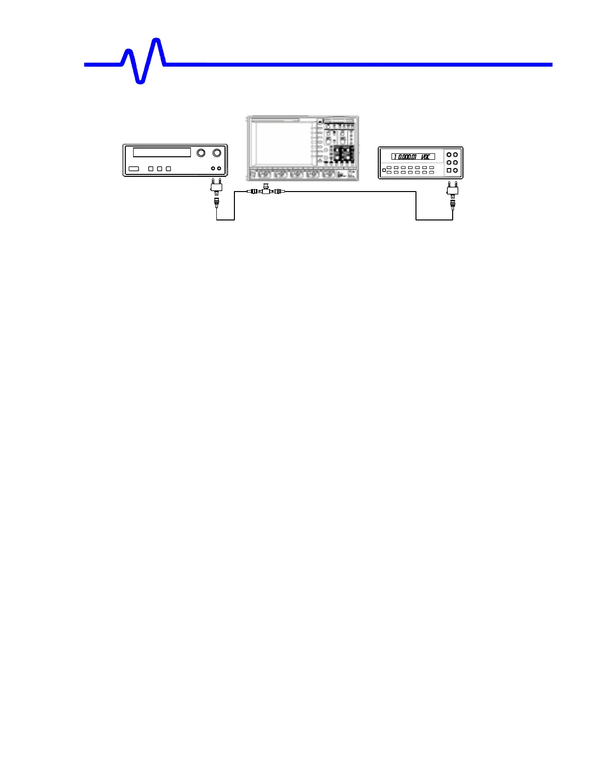
Figure 5-4 Offset Accuracy Test Setup
!
Set the output of the external
DC voltage reference source
to
−
−−
−
1 Volt
. (or
reverse the polarity of the banana jack adapter if the supply does not have
bipolar outputs)
1) Verify that the displayed trace A : Average (1) is on the screen, near the
center horizontal graticule line. If the trace is not visible, modify the
DC
voltage
reference source output
until the trace is within
±
2 divisions of center.
2) Connect the DMM and record the
voltage reading
in Table 6, column
DMM
.
3) Disconnect the DMM from the BNC T connector.
4) Press
Clear Sweeps
5) After 10 sweeps, Read off the
DSO Mean parameter
voltage, and
record the
measurement in Table 6, column
Mean
.
!
Repeat the test for the other channels, substituting channel controls and input
connector. Record the measurements in Table 6.
!
Repeat the test the other offset settings –1V and 0V.
Recall
xxxP020.PNL
for Input offset –1V.
Recall
xxxP021.PNL
for Input offset 0V.
Record the measurements in Table 6.
!
Calculate the
Difference (
∆
∆∆
∆
)
by subtracting the
DMM voltage
reading from
the
DSO mean
voltage reading.
!
Record the test result in Table 6, and compare the
Difference (
∆
∆∆
∆
)
to the
corresponding limit in the test record.
DC Power Supply
DMM
 Loading...


