7-8
E. Removal of the CPU Board
Remove the upper and bottom covers.
Remove the printer and floppy.
Remove the four M3 x 6 screws from the right and left frame.
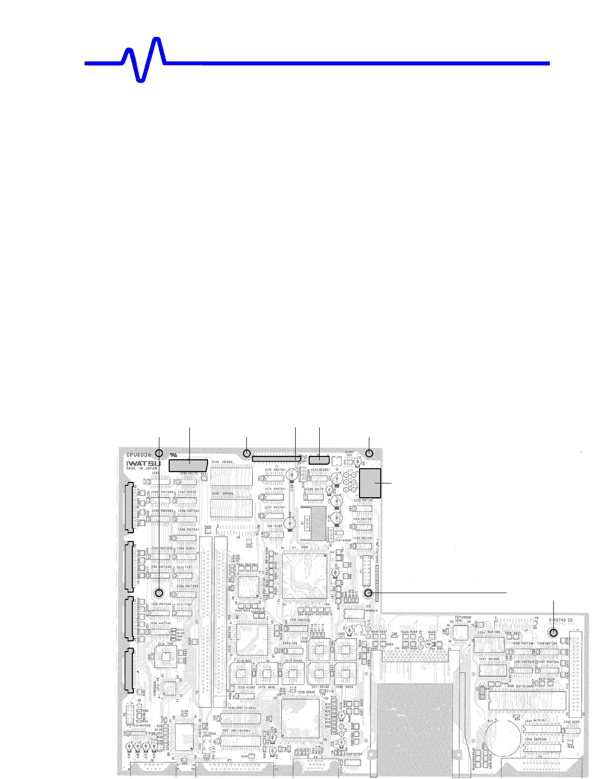
[Note] Remove the cables on the CPU Board and next the screws on it.
• E1 : Remove the four FFC cables on the CPU Board (J3/26pin, J4/22pin, J5/26pin,
J8/22pin).
• E1 : Remove the two FFC cables on the CPU Board (J1/30pin, J6/22pin).
• E1 : Remove the P5 power connector on the CPU Board (to LCD).
• E1 : Remove the P11 power connector on the CPU Board (to POWER).
• E2 : Remove the four M3 x 6 screws (4 on the rear, fastening between connectors and
between the rear panel and CPU).
Remove the eight M3x6 screws on the TOP FRAME L and R.
• E3 : Remove the six M3 x 6 screws on the CPU Board and remove the processor
broad by sliding it toward the front side.
Caution : Batteries are mounted, so care should be taken to prevent short-circuiting.
[E1]
Mechanical Parts & Removal
KB(+) 3x6S (NIP)KB(+) 3x6S (NIP)
J5
Front Side
J3
J8
J4
KB(+) 3x6S (NIP)
P5J1J6
P11
KB(+) 3x6S (NIP)

 Loading...

