SMB/EO1 Series
LECTROSONICS, INC.
10
The wiring diagrams included in this section repre-
sent the basic wiring necessary for the most common
types of microphones and other audio inputs. Some
microphones may require extra jumpers or a slight
variation on the diagrams shown.
It is virtually impossible to keep completely up to date
on changes that other manufacturers make to their
products, thus you may encounter a microphone that
differs from these instructions. If this occurs please
call our toll-free number listed under Service and
Repair in this manual or visit our web site at:
www.lectrosonics.com
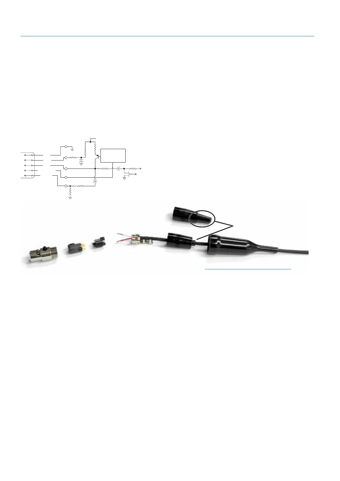
SM Equivalent Input Circuit Wiring
10k
1k
5
4
3
2
1
To Virtual Ground
Audio Amplifier
BIAS
MIC
BIAS SELECT
LINE IN
GND
+
30uF
+5 VDC
Servo Bias
Pin 4 to Pin 1 = 0 V
Pin 4 Open = 2 V
Pin 4 to Pin 2 = 4 V
+
To Limiter Control
30uF
500 Ohm
100 Ohm
2.7K
200 Ohm
+
3.3uF
100 Ohm
5-Pin Input Jack Wiring
Audio input jack wiring:
• PIN1 Shield(ground)forpositivebiased
electret lavaliere microphones. Shield (ground) for
dynamic microphones and line level inputs.
• PIN2 Biasvoltagesourceforpositivebiased
electret lavaliere microphones.
• PIN3 Lowimpedancemicrophonelevelinput
for dynamic microphones. Also accepts hand-held
electret microphones provided the microphone
has its own built-in battery.
• PIN4 BiasvoltageselectorforPin3.Pin3volt-
age (0, 2 or 4 volts) depends on Pin 4 connection.
Pin 4 tied to Pin 1: 0 V
Pin 4 Open: 2 V
Pin 4 to Pin 2: 4 V
• PIN5 Highimpedance,linelevelinputfortape
decks, mixer outputs, musical instruments, etc.
Installing the Connector:
1) If necessary, remove old connector from micro-
phone cable.
2) Slide Rubber Boot onto microphone cable with the
large end facing away from the microphone. (See
illustration above.)
3) If necessary, slide the 1/8-inch black shrink tubing
onto the mircrophone cable. (This tubing is needed
for some cables to ensure the cable fits snugly in
the rubber boot.)
4) Use the resistors and connector included with this
kit to configure the TA5F to your particular micro-
phone. A length of .065 OD clear tubing is included
if insulating the resistor leads or shield wire is
necessary. (Remove rubber strain relief from con-
nector backshell by pulling it out of the backshell.)
5) Slide the Strain Relief over the TA5F Insert and
crimp as shown to the right. Then insert the TA5F
Insert and Strain Relief in the TA5F Latchlock.
Screw the TA5F Flex Relief onto the TA5F Latch-
lock.
6) If needed, position and shrink the 1/8-inch shrink
tubing on the microphone cable, then slide the Rub-
ber Boot down over the TA5F connector.
TA5F Latchlock
Insert
Insulator
Cable clamp
TA5F Backshell
with Strain Relief
Remove strain relief
if using dust boot
TA5F Backshell
(Strain Relief
removed)
Dust Boot (35510)
Note: If you use the dust boot, remove
the rubber strain relief that is attached to
the TA5F cap, or the boot will not fit over
the assembly.