LECTROSONICS, INC.4
Audio Outputs
In addition to the audio outputs on the rear panel, the front panel of the
receiver provides a second set of outputs through a 5-pin connector. This
allows both audio channels to be connected through external cables for
cameras with only one audio channel enabled in the slot.
The TA5M connector provides two balanced outputs with the following
pinouts:
Pin 1 Pin 2 Pin 3 Pin 4 Pin 5
Shields CH1 + CH1 – CH2 + CH2 –
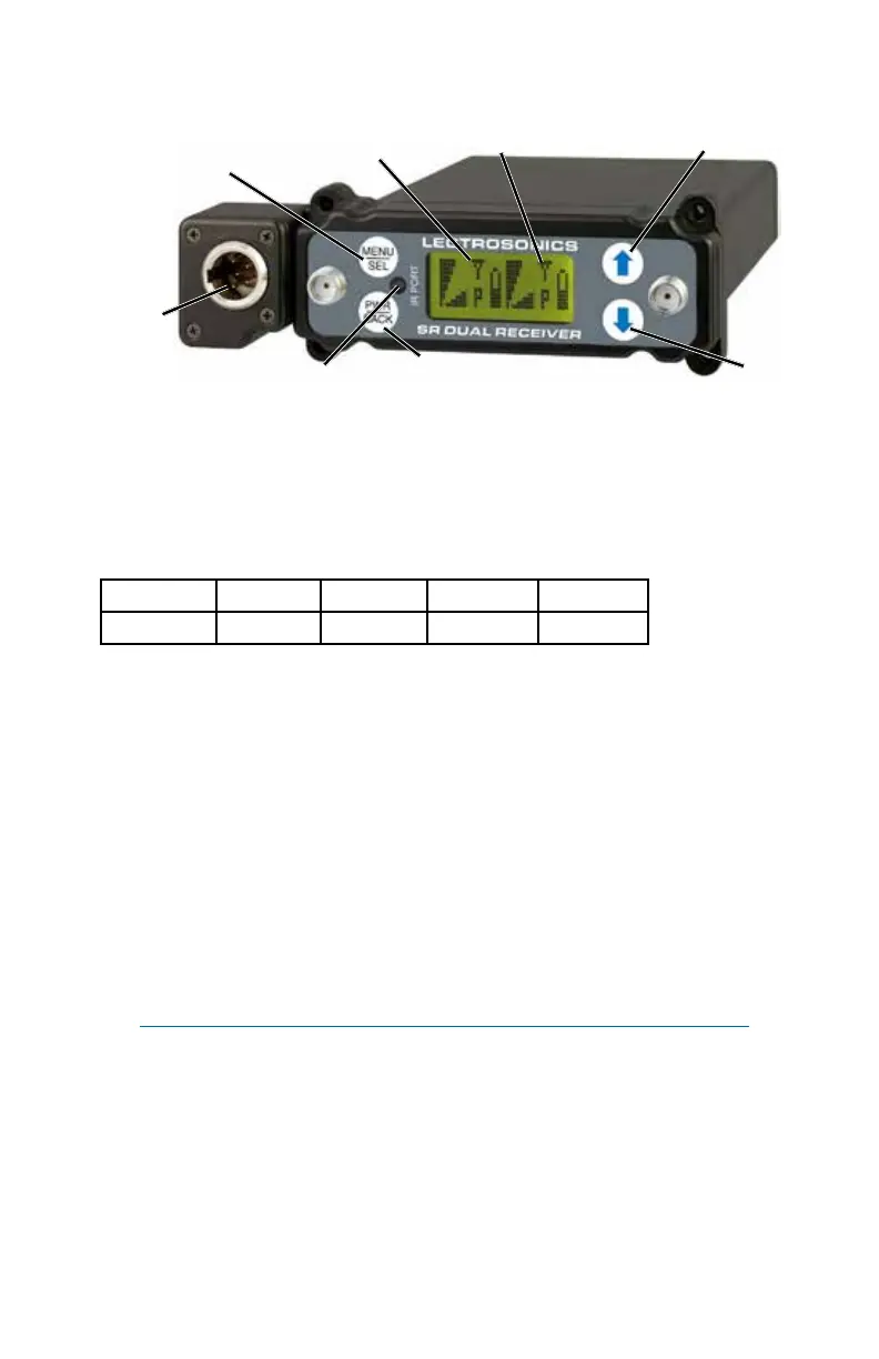
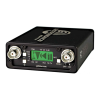
LCD Screen
A backlit, graphics-type LCD is used to set up and monitor the receiver.
The Main Window shown above is used during normal operation, to dis-
play RF and audio levels, transmitter battery status, pilot tone status and
diversity activity for both receivers.
MENU/SEL Button
This button is used to select menu items and enter setup screens during
setup.
IR (Infrared) Sync
An IR Sync Port is used for quick setup with transmitters that offer this
feature. Settings for frequency, step size, compatibility mode and talk back
are transferred from receiver to transmitter via the IR ports.
NOTE: Selected compatibility mode and talk back will only sync if
they are available options on the transmitter you are syncing with.
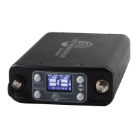
Front Panel Controls and Functions
DOWN
Button
MENU/SELECT
Button
POWER/BACK
Button
UP Button
Receiver 1
Receiver 2
Secondary
Audio
Output
IR Sync Port