Observe the following when using Ground Fault Circuit Interrupters (GFCIs):
• Installation of GFCI only between supplying mains and controller.
• The GFCI can be activated by:
- capacitive leakage currents between the cable screens during operation (especially with long,
screened motor cables)
- connecting several controllers to the mains at the same time
- RFI lters
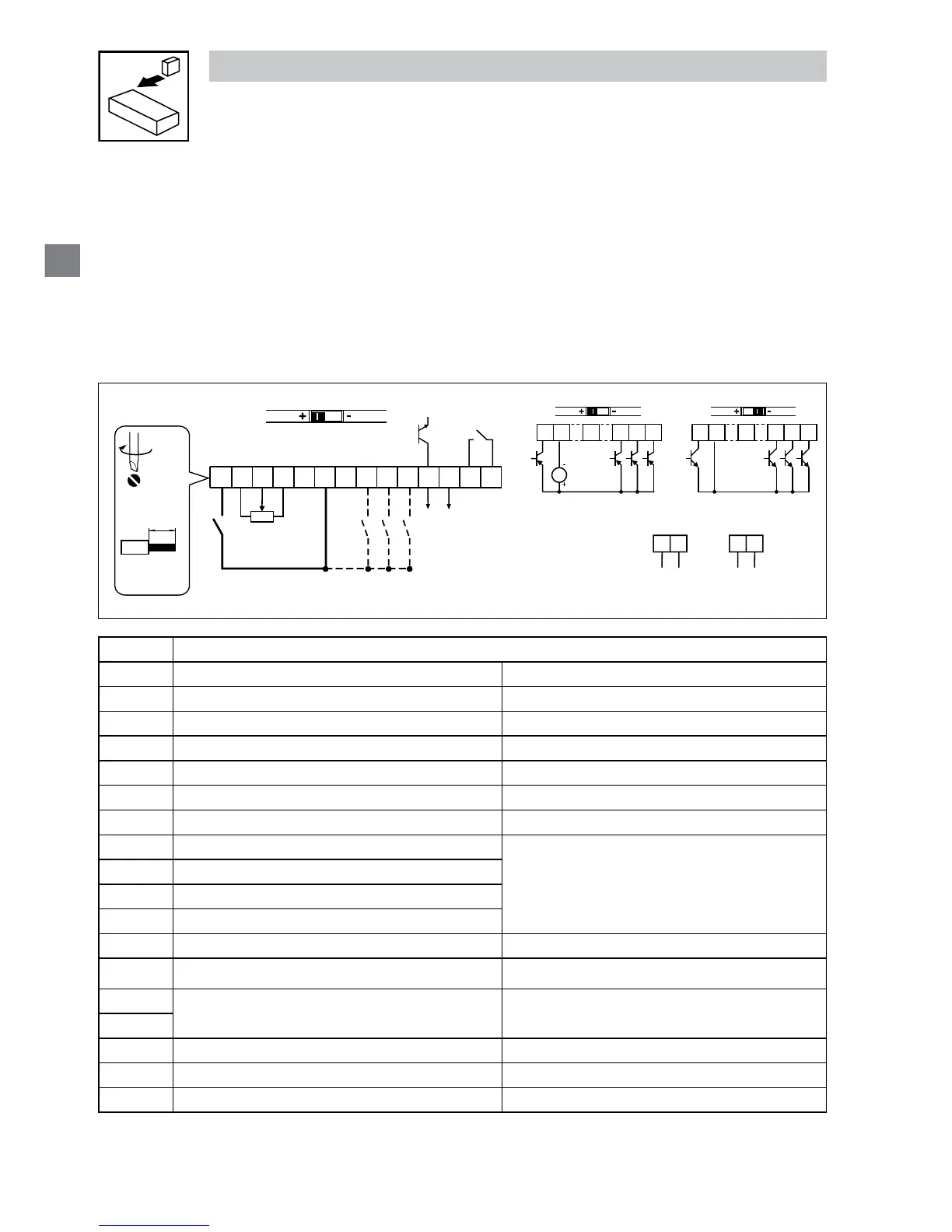
3.2.3 Control terminals
Control Terminal Strip for 0.33-10HP (0.25-7.5 kW):
625411
13A
13B
13C
17
512
14 30
16
AOUT
DIGOUT
2k … 10k
+10 V
AIN
AIN
COM
COM
252
4 … 20 mA
52
0 … 10 V
0 … 5 V
1 2 4
13A
13B
13C
+12 VDC - 0 %
…
+30 VDC + 0 %
ALsw
+15V
1 2 4
13A
13B
13C
ALsw
COM
PNP NPN
4.5 lb-in
(0.5 Nm)
0.25 in (6 mm)
AWG 26…16
(<1mm²)
V0109
Terminal Data for control connections
1
Digital Input: Start/Stop input resistance = 4.3kΩ
2
Analog Common
5
Analog Input: 0...10 VDC input resistance: >50 kΩ
6
Internal DC supply for speed pot +10 VDC, max. 10 mA
25
Analog Input: 4...20 mA input resistance: 250Ω
4
Digital Reference/Common +15 VDC / 0 VDC, depending on assertion level
11
Internal DC supply for external devices +12 VDC, max. 50 mA
13A
Digital Input: Congurable with P121
input resistance = 4.3kΩ
13B
Digital Input: Congurable with P122
13C
Digital Input: Congurable with P123
13D*
Digital Input: Congurable with P124
14
Digital Output: Congurable with P142 DC 24 V / 50 mA; NPN
30
Analog Output: Congurable with P150…P155 0…10 VDC, max. 20 mA
16
Relay output: Congurable with P140
AC 250 V / 3 A
DC 24 V / 2 A … 240 V / 0.22 A, non-inductive
17
2*
Analog Common
TXA*
RS485 TXA
TXB*
RS485 TXB
* = Terminal is part of the terminal strip for the 15-25 HP models only
 Loading...