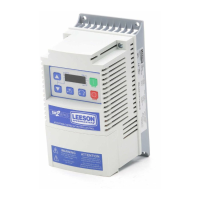
EasyManuals Logo

Leeson SPEEDMASTER SM2 Series User Manual

Leeson SPEEDMASTER SM2 Series
70 pages
To Next Page IconTo Next Page
To Previous Page IconTo Previous Page
Page #18 background imageLoading...
Page #18 background image
17
Commissioning
Control Terminal Strip for 15HP (11 kW) and Greater Drives:
625411
13A
13B
13C
TXA
512
14 30
2
AOUT
DIGOUT
2k … 10k
+10 V
+12 V
AIN
AIN
COM
COM
ALsw
17
16
TXB
13D
13D
13D
252
4 … 20 mA
52
0 … 10 V
1 2 4
13A
13B
13C
+12 VDC - 0 %
. . .
+30 VDC + 0 %
ALsw
+15V
1 2 4
13A
13B
13C
ALsw
COM
4.5 lb-in
(0.5 Nm)
0.25 in (6 mm)
AWG 26…16
(<1mm²)
The digital inputs can be congured for active-high or active-low by setting the Assertion Level
Switch (ALsw) and P120. If wiring to the drive inputs with dry contacts or with PNP solid state
switches, set the switch and P120 to “High” (+). If using NPN devices for inputs, set both to
“Low” (-). Active-high (+) is the default setting.
HIGH = +12 … +30 V
LOW = 0 … +3 V
Note
An F.AL fault will occur if the Assertion Level switch (ALsw) position does not match
the parameter P120 setting and P100 or any of the digital inputs (P121...P123) is set
to a value other than 0.
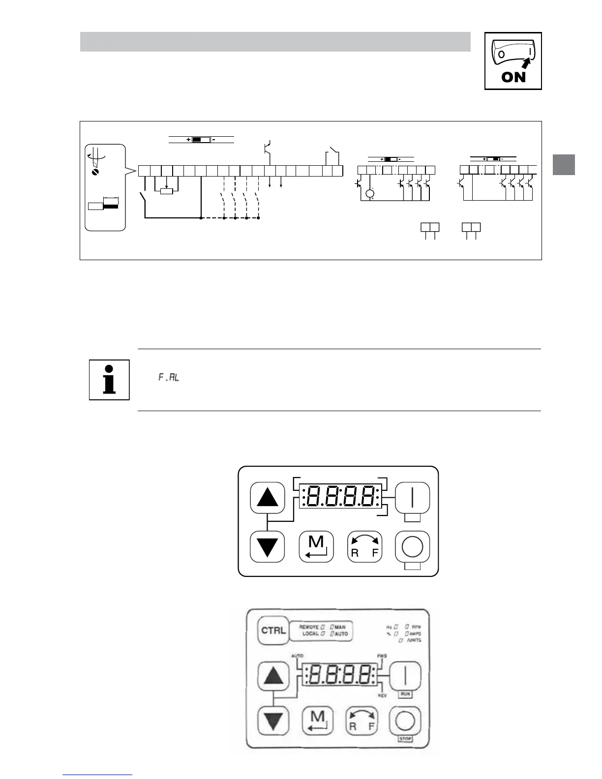
4 Commissioning
4.1 Local Keypad & Display
FWDAUTO
REV
STOP
RUN
V0105
15HP (1kW) and greater Models
CALL NOW 800-985-6929
http://www.automatedpt.com
Email: charles@automatedpt.com
CALL NOW 800-985-6929
http://www.automatedpt.com
Email: charles@automatedpt.com

Questions and Answers:

Question and Answer IconNeed help?

Do you have a question about the Leeson SPEEDMASTER SM2 Series and is the answer not in the manual?

Leeson SPEEDMASTER SM2 Series Specifications

General IconGeneral
BrandLeeson
ModelSPEEDMASTER SM2 Series
CategoryDC Drives
LanguageEnglish

Related product manuals