Code
Display Range
(READ ONLY)
IMPORTANT
No. Name
P562
Sequencer: Time
Remaining in
Active Segment
0.0 {P708} 6553.5
0 {P708} 65535
Unit depends on P708 (0.1sec, sec or minutes)
P563
Sequencer:
Number of
cycles since
start
0 65535
P564
Sequencer:
Number of
cycles remaining
0 65535
Note: Parameters P560-P564 are visible only when P700 > 0 (i.e. the
sequencer is enabled)
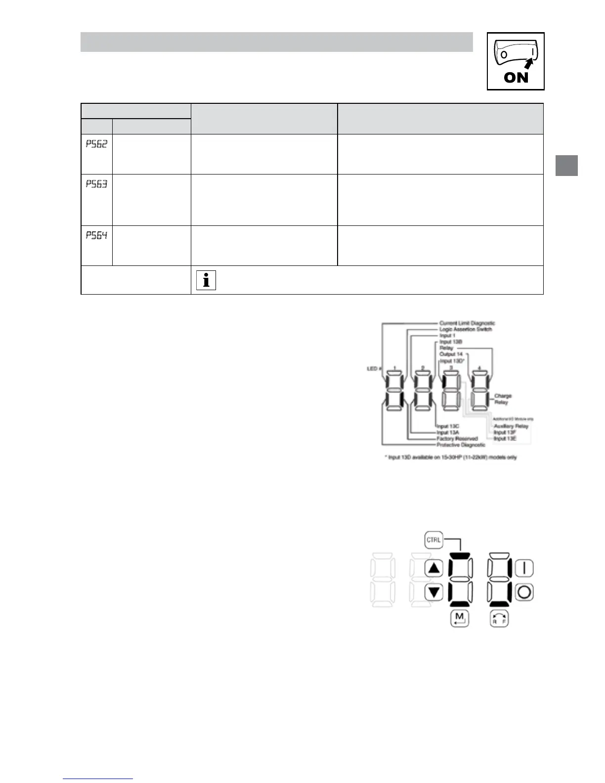
4.5.7.1 Terminal and Protection Status Display
Parameter P530 allows monitoring of the control terminal
points and common drive conditions:
An illuminated LED segment indicates:
• the protective circuit is active (LED 1)
• the Logic Assertion Switch is set to High (+)
• input terminal is asserted (LED 2)
• output terminal is energized (LED 4)
• the Charge Relay is not a terminal, this segment will
be illuminated when the Charge Relay is energized
(LED 4)
4.5.7.2 Keypad Status Display
Parameter P531 allows monitoring of the keypad
pushbuttons:
An illuminated LED segment indicates when the button
is depressed.
LED 1 and LED 2 are used to indicate pushbutton
presses on a remote keypad that is attached to the
drive. LED 3 and LED 4 indicate button presses on the
local drive keypad.
 Loading...