Code Possible Settings
IMPORTANT
No. Name Default Selection
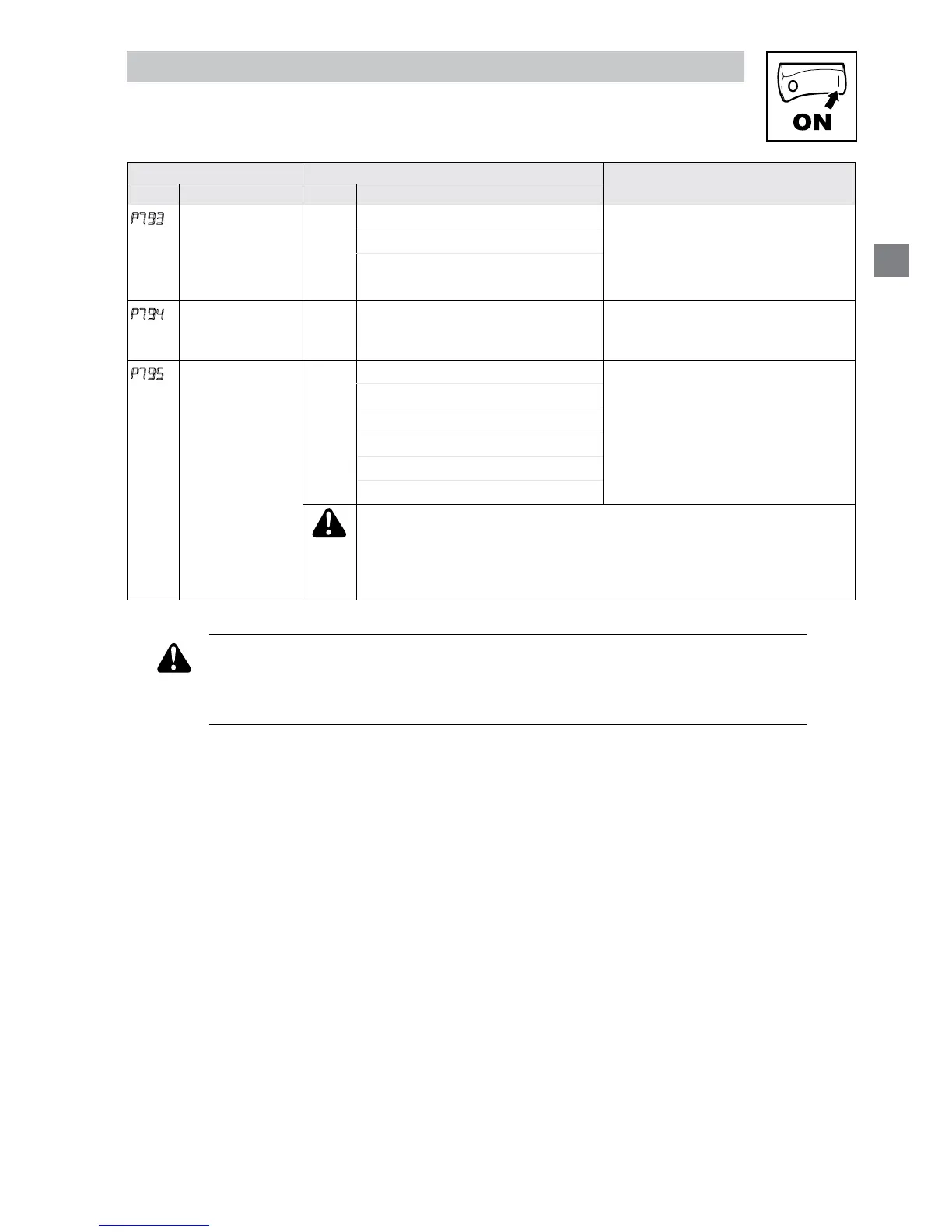
P793
End Segment:
Digital Output
State
Bit0 Relay bit = 0: OFF (De-energized)
bit = 1: ON (Energized)
The corresponding digital output/
relay must be set to accept value the
from the sequencer: P140, P142=27
Bit1 TB14
P794
End Segment:
TB30 Analog
Output Value
0.00
0.00 {VDC} 10.00 TB30 conguration parameter must
be set to accept this value: P150
= 10
P795
End Segment:
Drive Action
0
0 Keep Running Recovery: Toggling the START
SEQUENCE will start the cycle
from ‘end segment Stop’ or ‘end
segment DC Brake’.
1 Stop (based on P111)
2 Coast to Stop
3 Quick Stop
4 Coast with DC Brake
5 Ramp with DC Brake
WARNING!
If P795 = 0 then toggling the start sequence input will also restart the
sequencer cycle but in the interim where TB13X is open the drive will
ramp to the standard or specied alternate speed source depending on
the drive conguration.
WARNING
If the input dened to “Start Sequence” is opened during a sequence, the
drive will exit sequencer mode and will run at the specied standard or
alternate speed source (dependent on drive conguration).
 Loading...