Physical configuration is completed by fitting special connection
components called configurators in appropriate housings of each
device, using a special tool. Configurators are distinguished by
numbers, letters, colour, or graphic representations.
This procedure is recommended for low or medium complexity
systems. For systems consisting of several devices, for houses
on several floors, hotels and the service sector, the virtual
configuration described in the following pages is recommended.
PHYSICAL CONFIGURATION
The configuration is a necessary for assigning an address to
the device within the system and set its operating mode.
A preliminary definition of the configuration, will help identify
which functions should be included in the system, how
many devices should be installed, and where they should be
installed within the house. Two types of configuration are
possible: physical configuration and virtual configuration.
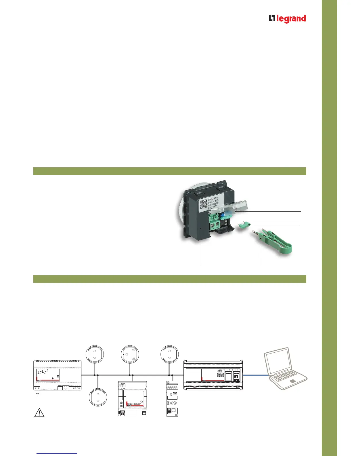
Numbered
configurator
Configurator
housings
Description of the
configurator housings
Tool for the fitting
of the configurator
For systems with several devices, the configuration process may
be greatly simplified by using, computer, as an alternative to the
manual configuration procedure.
This type of configuration, called “virtual configuration”, makes it
possible to configure each device without the use of the standard
alphanumeric configurators. The address and the operating
mode of the device is set using a special software installed on the
computer; this solution is particularly suited to large system, as
it allows modification of the configuration at any time, without the
need for manual intervention on each device.
Virtual configuration may be used only in Automation systems:
both in individual systems, and also in case of several systems
integrated with each other in “logic extension” mode.
VIRTUAL CONFIGURATION
 Loading...