point-point control
group
control
room
control
actuators
SCS BUS
general control
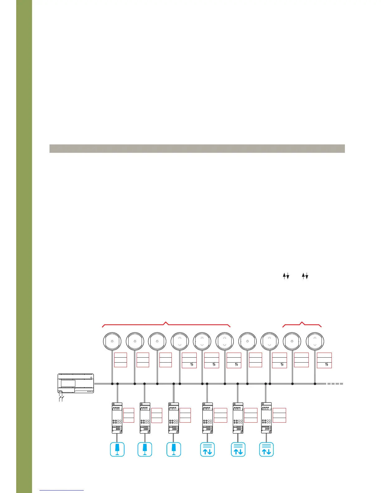
Configuration example
Definition of the addresses
Point-point control
Control N° 1 (A=1, PL=1) controls actuator N° 1 (A=1, PL=1 and
G=1); in the same way, control N°2 (A=1,PL=2) controls actuator
N°2 (A=1, PL=2 and G=1) etc...
Room control
Room control no. N°8 (A=AMB, PL=2) controls actuators N° 4 and
5 marked with A=2.
Group control
Group control N° 7 marked with A=GR and PL=1, controls
actuators N°1 and 2 marked with G=1.
General control
M position to define the function (ON/OFF or UP/DOWN).
The devices identified as A=GEN and PL=- (no configurator),
send a general control to all actuators within the system, for the
control of lights and the shutters.
NOTE:
Differently from light actuators, the actuators for the
management of shutters are configured both in position PL1 and
PL2.
The drawing shows a system for the management of three light
points and three shutters. Each actuator is identified by three
numbers: Room number (A), progressive device number (PL for
the lights, and PL1 and PL2 for the shutters actuators), and the
Group (G) they belong to.
On the other hand, the control devices are fitted with configurators
in the A and PL position. They specify the addresses of the
actuators receiving the control (only one, a group, or several
actuators of a room). They are also fitted with configurators in the
M positon for the definition of the function (ON/OFF or UP/DOWN).
Operating modes of controls
T
he configurator fitted to position M of each control device defines
the operating mode. The O/I configurator specifies a light switch on
control, performed using the upper key cover (ON) and the bottom
key cover (OFF).
On the other hand, the configurators and M in the M
position specify a control for the management of shutters, for
actuators No. 4, 5 and 6.
Basic configuration concepts
A = 1
PL = 1
M = O/I
A = 1
PL = 2
M = O/I
A = 1
PL = 3
M = O/I
A = 2
PL = 1
M =
M
A = 2
PL = 2
M =
M
A = 3
PL = 1
M =
M
A = GR
PL = 1
M = O/I
A = AMB
PL = 2
M =
M
A = GEN
PL = —
M =
M
A = GEN
PL = —
M = O/I
A = 2
PL1 = 1
PL2 = 1
A = 3
PL1 = 1
PL2 = 1
A = 2
PL1 = 2
PL2 = 2
A = 1
PL = 1
G = 1
A = 1
PL = 2
G = 1
A = 1
PL = 3
G = 2
230 Vac