_____________________________________________________________________________________________________
35
3 – CONNECTION
A – PROTECTION
Capacitor banks not equipped as standard with a general protection system must always be
fitted with one. It should be installed at the start of the power supply cable with:
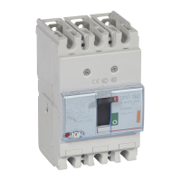
A circuit breaker:
o with a thermal relay
(1)
set to 1.4 x In minimum
o with a magnetic relay
(1)
set to between 8 and 10 x In
A gG type HPC switch-fuse, with a rating of 1.4 x In minimum
B – POWER CIRCUIT
The recommendations below must be followed when connecting capacitor banks to the main
power supply:
The power cables used for connection must have minimum dimensions of:
I = 1.43 x In
(2)
The cross-section calculation must take account of the usual coefficients associated with
the cable type:
o Type
o Length
o Installation method
Phases L1/L2/L3 must be connected as marked on the internal busbar.
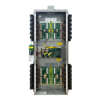
For enclosures made up of several cubicles, the busbar in each cubicle MUST be
connected to the upstream power supply via power cables of the same quantities
and cross-sections in order to ensure balanced distribution of the currents
(1)(3)
.
The capacitor bank must be earthed with a cable whose cross-section complies with the
current standard.
(1)
To help you choose, you can consult the table on page 36.
(2)
See the table of recommended cross-sections for the power supply cables on page 36.
(3)
Except on versions with built-in general protection system.
 Loading...