Wattstopper
®
Low Voltage, 0–10V PIR Occupancy Sensor In IP65 Enclosure with
DALI and Bluetooth
®
Low Energy Technology
Détecteur de mouvements à infrarouge passif 0–10V basse tension
dans boîtier IP65 avec DALI et Bluetooth
Sensor de presencia PIR de 0–10V bajo voltaje y bajo consumo de
energía en carcasa IP65 con tecnología DALI y Bluetooth
Installation Instructions • Instructions d’Installation • Instrucciones de Instalación
No: 28165 – 02/22 rev. 6
Catalog Number • Numéro de Catalogue • Número de Catálogo: FDP-301
Country of Origin: Made in China • Pays d’origine: Fabriqué en Chine • País de origen: Hecho en China
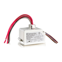
SPECIFICATIONS
Input Voltage ................................................................12–20VDC
Power Consumption from DALI Bus .................................... 16mA
Wiring ..........................................................................16–20AWG
Terminal Connection ...................DC+, Dim +, Dim – / SR –, SR +
Operating Temperature ....................... -40F (-40C) to 167F (75C)
Dimensions ........................... Diameter (83mm), Height (67.4mm)
Enclosure ............................................... IP65 (NEMASTD) , IK09
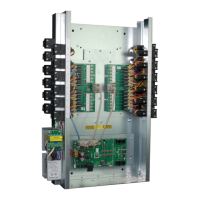
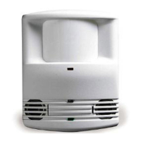
DESCRIPTION AND OPERATION
The FDP-301 sensor is a low voltage passive infrared sensor with continuous dimming that is compatible with 0–10v (with Dim OFF)
drivers or DALI drivers. The device is available with an integrated terminal block that can be wired to support either driver technology.
The threaded mount allows you to install on standard 1” KOs. The device can be commissioned locally with the Wattstopper Sensor
Configuration App or through a compatible network lighting controller (compatibility pending).
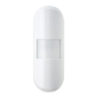
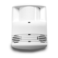
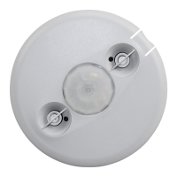
LENS OPTIONS AND COVERAGE
The FDP-301 is available with two different lens options. The L2 lens provides coverage at a height of up to 15 feet, while the L7 lens provides
coverage for a height of up to 40 feet. The L2 and L7 are multi-cell, multi-tier Fresnel lenses with a 360° view. The coverages shown in the
diagrams are maximum, measured in linear feet. They represent coverage for full-step walking motion, with no barriers or obstacles.
Passive Infrared Sensing in Outdoor Environments
Outdoor environments can have ambient temperature variations that may affect sensor detection and coverage areas. High
temperatures at the covered area (above 80°F) reduce the detection zone of the sensor. Consider adding more sensors if the ambient
temperatures are expected to be high. Additionally, high floor level temperature may require larger movement for detection. In some
cases, sensors mounted above 40’ may only detect large heat signatures such as automobiles.
FDP‑L2: 360°
Coverage
The FDP-L2 is designed
for mounting at heights
between 8’ to 15’. It
provides a 48’ diameter
coverage area when
mounted at a height
of 8’, or a 78’ diameter
coverage area at 15’.
’
24’24’09’ 9’12’ 12’16’ 16’
48
0
8’
16.5’26’30’39’
12’
15’
16.5’ 26’ 30’ 39’
Coverage Top View @ 8ft.
Coverage Side View
0'
10' 10'
20' 20'30' 30'40' 40'
50'50'
Coverage Top View @40ft
Coverage Side View
0'
100'
FDP‑L7: 360°
Coverage
The FDP-L7 has a
lens that covers a 100'
diameter area at a
height of 40'.