2
MOUNTING AND WIRING
1. Determine an appropriate mounting location inside the
light fixture minimizing the electric light contribution to
the sensor’s photocell. Allow a minimum distance of 0.2”
(5.1mm) from the wiring end of the sensor to the wall of the
fixture.
2. Drill a hole 1.30” (33.0mm) in diameter through the sheet
metal in the bottom of the fixture.
3. Add the rubber gasket to the threaded collar, and install the
sensor face down, parallel to the mounting surface. Ensure
the rubber gasket touches the inside surface of the fixture.
Install the plastic nut securely against the fixture to a torque
of 25–30 in-lbs.
4. Connect wires as shown in wiring diagrams.
5. Restore power from the circuit breaker.
NOTE: Per UL, the 0-10V negative dimming wire color has been changed
from gray to pink.
MASKING THE LENS
The optional FDP-M1 mask provides
the ability to limit coverage areas for
example, in hallways or multi-use
environments. The mask has three 90°
sections. One or two of the sections
can be removed, to provide different
coverage patterns. Snap the mask
onto the lens and rotate to the desired
position.
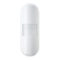
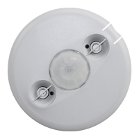
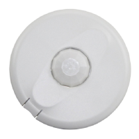
FDP‑301 COMPONENTS
Blue LED
Reset Button
WARNING: TURN THE POWER OFF AT
THE CIRCUIT BREAKER BEFORE WIRING.
Tightening Nut
Fixture
Wall
Outside
Fixture Wall
Inside Fixture
Wall
Driver
Driver
Tightening Nut
Rubber
Gasket
Rubber
Gasket
Neutral (White)
Line (Black)Ground (Green)
SR+ (Yellow)
SR– (Pink)
DALI Driver
DALI WiringFDP‑301 Wiring Terminals
Neutral (White)
Line (Black)Ground (Green)
0-10V– (PInk)
0-10V+ (Purple)
0–10V Driver
(with Aux Power)
DC+ (Red)
0–10V Wiring
FDP‑301 CONFIGURATION WITH THE SENSOR CONFIG APP
The Sensor Configuration App is available for both iOS
®
and Android
®
devices. Search
“Wattstopper Sensor Config” on your device to download.
NOTE: Bluetooth communication ranges can vary depending on the device,
as well as mobile carrier. Wattstopper recommends devices with
Bluetooth 5.0. Iphone 8 and Samsung Galaxy S8 and later devices are
recommended for optimal performance.
The Sensor Configuration tool is a mobile app for changing defaults and testing of the
FDP-301. It provides wireless access to the FDP-301 sensors for parameter changes and testing. Within
a certain mounting height of the sensor, the Sensor Configuration app allows modification of the system
without requiring ladders or tools.
If no configuration steps are taken, the sensor will use its default parameter values.
The Sensor Configuration app display shows menus and prompts to lead you through each process. The
mobile app provides a simple way to navigate through the customization fields.
The Sensor Configuration app allows bi-directional communication between the FDP-301 and the mobile
app. Simple menu screens let you see the current status of the sensor and make changes. It can change
FDP-301 sensor parameters such as high/low mode, sensitivity, time delay, cut off and more. With the
Sensor Configuration app you can also establish and store FDP-301 parameter profiles and enable continuous dimming.