GR30/GM30/GR50, Pin Assignments and Sockets
84
B.2 GR50
Description Some applications require knowledge of the pin assignments for the GR50 ports. In
this chapter, the pin assignments and sockets for the ports of the GR50 are explained.
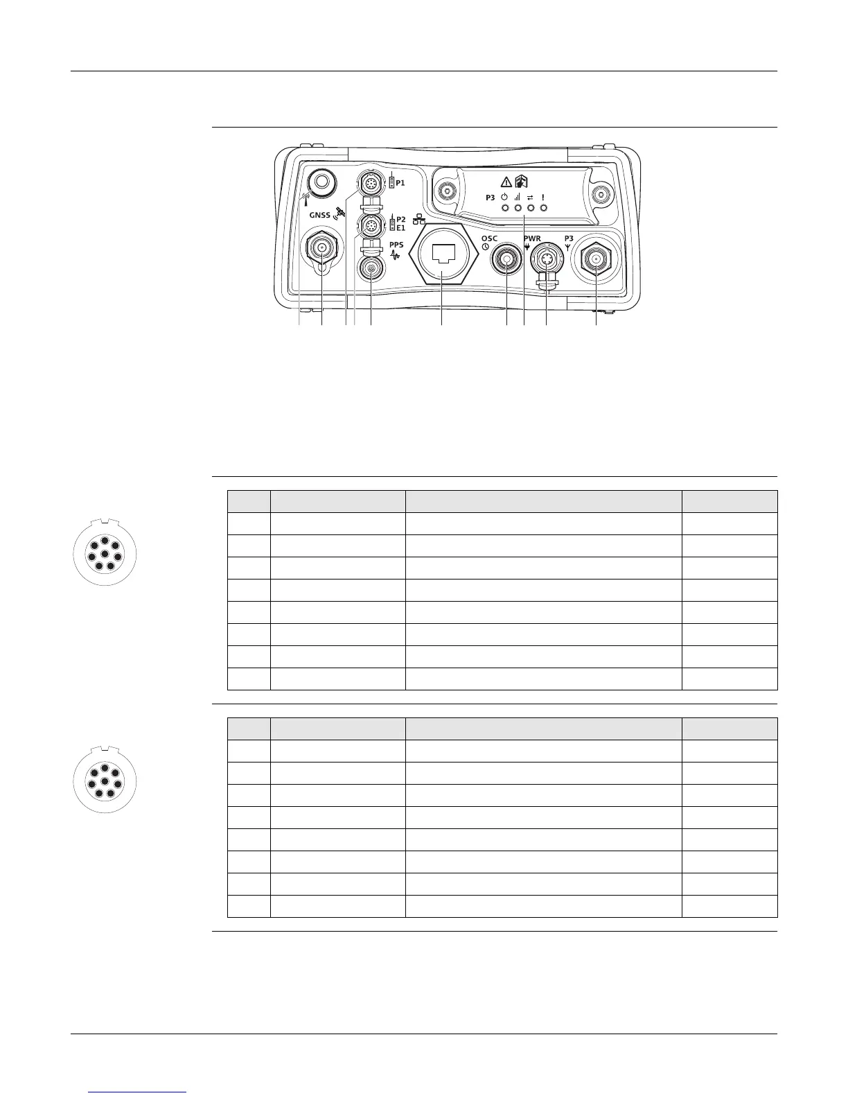
Ports on the
instrument rear
panel
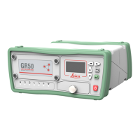
Pin assignments for
P1: Serial Port
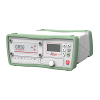
Pin assignments for
P2: Serial Port
a) BT/WLAN: BT/WLAN antenna
b) GNSS:GNSS antenna port TNC
c) P1: Serial port, 8 pin LEMO
d) P2: Serial/Event port, 8 pin LEMO
e) PPS: Pulse per second output
f) Ethernet port: Ruggedised RJ45
g) OSC: Oscillator port
h) P3: Communication slot-in port
i) PWR: Power port, 5 pin LEMO, dual input
j) P3: Communication slot-in port antenna,
TNC
GR25_006
b e fhg ijc da
1
7
6
8
5
4
3
2
PIN_003
Pin Signal Name Function Direction
1 RTS RS232, ready to send Out
2 CTS RS232, clear to send In
3 GND Signal ground -
4 RxD RS232, receive data In
5 TxD RS232, transmit data Out
6 ID Indentification pin In or out
7 GPIO RS232, configurable function In or out
8 +12 V12 V power supply out Out
1
7
6
8
5
4
3
2
PIN_003
Pin Signal Name Function Direction
1 RTS RS232, ready to send Out
2 CTS RS232, clear to send In
3 GND Signal ground -
4 RxD RS232, receive data In
5 TxD RS232, transmit data Out
6 ID Indentification pin In or out
7 GPIO / EVT IN RS232, general purpose input/output In or out
8 +12 V12 V power supply out Out