21
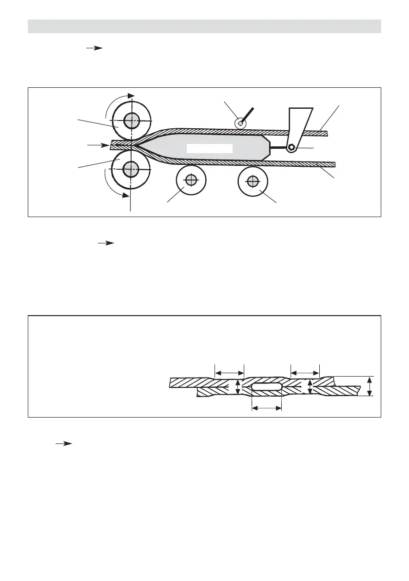
Seam thickness reduction = A – B
A : Thickness of the upper and lower membrane
B : Thickness of the welded seam
C : Welded section 1
D : Welded section 2
E : Test channel
B
CD
A
B
E
HOT WEDGE
Welding direction
Upper geomembrane liner
Pinch roller
Lower geomembrane liner
Cross-sectional diagram of hot wedge system
Rear guide roller
Lower dirve/
pressure roller
Upper drive /
pressure roller
Front guide roller
Adjustment screw
hot wedge
Cross sectional diagram of an overlap weld
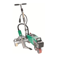
• Welding Pressure steplessly adjustable. The welding pressure is transmitted via a toggle lever to the
pressure rollers. The swivel head guarantees the equalisation of the pressure to both welded sections
(C and D) as well as on a welded seam without test channel.
This allows T-joints to be welded easily. During the welding process the pressure adjusts itself linearly to the
change in material thickness of the geomembrane liner.
• Drive Double drive system, is steplessly adjustable and elec tron ically controlled. The automatic control
system with tachogenerator is designed in such a way, that the adjusted welding speed remains constant
independently of the load. The power transmission to the drive/pressure rollers works through a three stage
planetary gear.
• Heating system The hot air temperature is steplessly adjustable and electronically controlled. According to
the material thickness the hot wedge position can be steplessly adjusted as required.
Description of functions