29
— Adjustment of the hot wedge with two heating cartridges
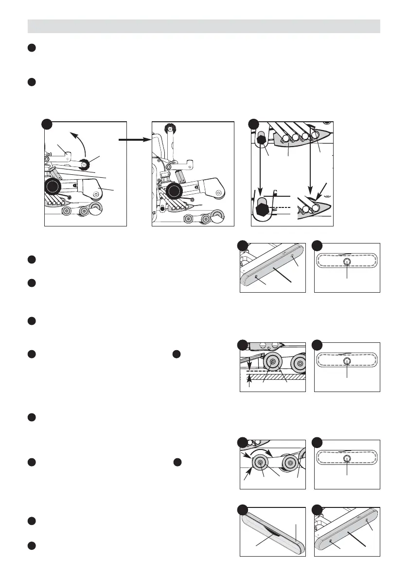
Adjust the front guide roller (18) by turning the hexagon socket screw (33) (on the front face of the
guide roller) anti-clockwise using an Allen key. The distance from the floor to the front guide roller (18)
must be 1 mm plus the film thickness.
Tighten the hexagon socket screw (26). The hexagon
socket screw (33) (on the front face of the guide roller) must
be held at the same time with an Allen key.
— Adjustment of the hot wedge with three or four heating cartridges
Using an Allen key, turn the front guide roller (18) by means of the hexagon socket screw (33) – on the
front face of the guide roller – in the direction of the drive rollers (20) and into the centre of the lower part
of the chassis (23).
The lower part of the chassis (23) serves as an aid to orientation
Tighten the hexagon socket screw (26). The hexagon
socket screw (33) (on the front face of the guide roller)
must be held at the same time with an Allen key.
— Adjustment of the front guide roller (18)
Slacken screw (31) and remove the lower part of the chain
guard (25).
Slacken the hexagon socket screw (26).
Press the lever locking mechanism (12) to the side and at the same time rotate the lever for welding
pressure (9) upwards. Manually loosen the locking screw (11). Using the adjusting screw for welding
pressure (10) adjust the clamping arm (31) to maximum opening.
Slacken the hot wedge adjustment screw (27). The hot wedge (7) should slope slightly downwards.
Air gap between film guide (32) and hot wedge (7) approximately 1 mm. Tighten the hot wedge
adjustment screw (27) in the lower third of the elongated hole.
26
31
31
18
33
25
C
31
31
25
C
D
26
D
26
DE
25
35
G
Adjusting the hot wedge and the guide roller
A
B
9
12
11
31
10
A B
27 7
32
2/3
1/3
1 mm
1mm
18
33
23
F
C
D
E
ED
F
FD
— Fitting the lower part of the chain guard (25)
It must be observed that the chain tensioner (35) (inside
the chain guard) lies on top.
Secure the lower part of the chain guard (25) with the
screws (31).
G
C
20