30
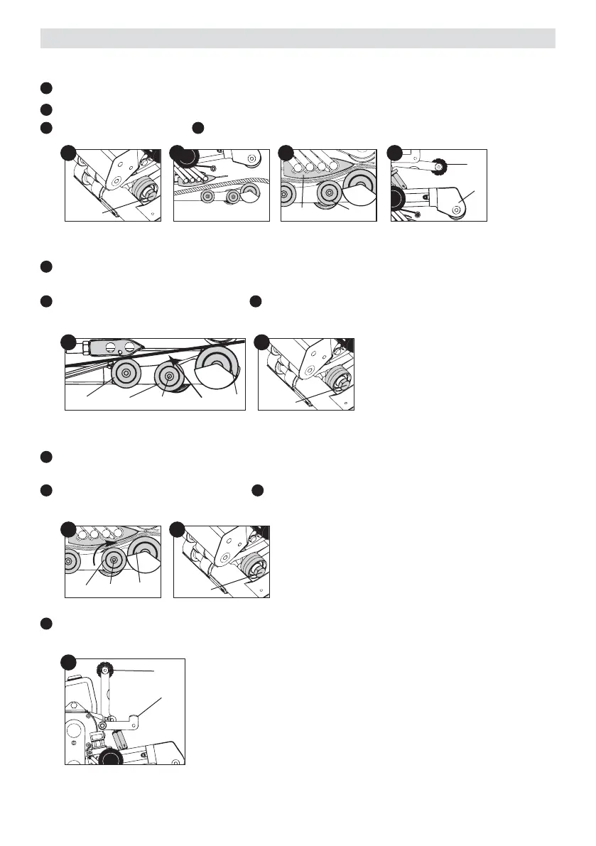
Slacken the lever locking mechanism (12) and at the same time
release the lever for welding pressure (9). Remove the test material.
— Adjusting the hot wedge with three or four heating cartridges
Turn the rear guide roller (19) clockwise against the film. While doing so, the rear guide roller (19) must
contact the film and there must be a noticeable resistance to turning.
Tighten the hexagon socket screw (32). The hexagon socket screw (34) (on the front face of the guide
roller) must be held at the same time with an Allen key.
— Adjusting the hot wedge with two heating cartridges
The front guide roller (18) and rear guide roller (19) must form a straight line with the pressure
roller (20), whereby the rear guide roller (19) is adjusted to approximately 2 mm under the line.
Tighten the hexagon socket screw (32). The hexagon socket screw (34) (on the front face of the guide
roller) must be held at the same time with an Allen key.
32
H
32
H
32
HO
I L
9
31
9
12
18
19
34
M
2 mm
M
MH
O
H
P
O
Adjustment of the hot wedge and the guide roller
— Adjustment of the rear guide roller (19)
Slacken the hexagon socket screw (32).
Insert the material to be welded. Adjust the welding pressure (see Page 23).
Engage the hot wedge (7). Tension the clamping arm (31) using the lever for welding pressure (9).
H
I
K L
20
19
7
K
20
19
P
34