31
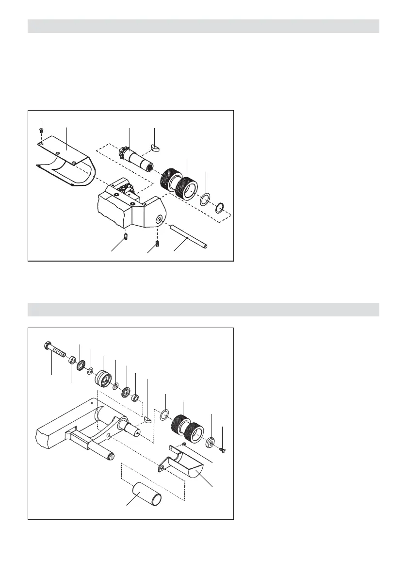
Dismantling of the drive/pressure rollers, sequence 1 – 16
Assembly of the drive/pressure rollers, reverse 16 – 1
1 Countersunk screw M3 × 6
2. Cylinder screw M8 × 40
3 Spacer bush
4 Nilos-ring ø 8/20 × 1,8
5 Shim ø 8/14 × 0,1
6. Rear travelling wheel complete
7 Shim ø 8/14 × 0,1
8 Nilos-ring ø 8/20 × 1,8
9 Spacer bush
10 Guide roller
11 Guard plate drive/pressure roller
12 Countersunk screw M4 × 12
13 Locking washer
14 Drive/pressure roller
15 Spacer ø 15/22 × 0,3
16 Woodruff key 5 × 6,5
10
1
11
16
15
14
13
12
9
8
2
3
4
5
6
7
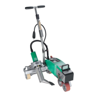
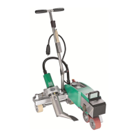
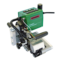
For various applications, for example tunnel construction or civil engineering at or below ground level, various
overlap-welded seams can be manufactured with the LEISTER Comet. These differ in the width of the welded
seam and the width of the test channel. Also welded seams without a test channel can be manufactured. In
order to implement these different overlapped seams, the appropriate drive/pressure rollers must be fixed.
These drive/pressure rollers can be produced in aluminium or stainless steel according to the customer’s
requirements.
Dismantling of the drive pressure rollers, sequence 1 – 9
Assembly of the drive/pressure rollers, reverse order 9 – 1
1 Countersunk screw M3 × 6
2 Guard plate for swivelling head
3 Set screw M4 × 8
4 Straight pin 6 × 80
5 Locking ring (shaft ø 15)
6 Spacer ring
7. Drive/pressure roller
8 Woodruff key
9 Drive shaft, upper complete
1
2
9 8
7
6
5
3
3
4
Changeover of upper drive / pressure roller
Changeover of lower drive / pressure roller