14
MAINTENANCE (DC-2000, DC-3100, DC-4600 & DC-7700)
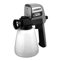
SPRAY GUN:
The filter should be cleaned or replaced after each use to minimize tip
clogging problems. If the gun valve becomes worn and begins to leak, it
should be replaced. See L-65 section for overhaul details.
SPRAY TIP:
The spray tip is one of the most important elements in producing a
quality spray job. It requires periodic replacement (every 50-200 gallons)
to maintain performance and to prevent overworking the pump (see Tip
Selection section for details).
LOWER PACKINGS:
No regular service required.
The lower packings of these units are stationary, so that the only metal
wearing parts are the valves and the piston. Costly replacement of the
pump cylinder is eliminated. The lower packings are self adjusting, and
will generally outlast the upper packings. Both sets are included in the
packing kit, and should be changed together for best reliability and
performance. On the DC-7700 the lower packings can be re-thightened
after every 2000 gallons of paint has been sprayed. Simply rotate the
inlet valve housing 1/8 of a turn clockwise to adjust the spring tension on
the packings.
UPPER PACKINGS:
Lubricate daily with 2 to 3 drops of L034-125 oil. Oiling location is shown
on pages 6 & 7. The upper packings are adjusted manually, by turning
the brass packing nut to the left, ie; clockwise as viewed from the top.
Keep guard in place during operation.
IMPORTANT NOTE: The packings should never be over tightened,
as this greatly reduces packing and piston life. Never tighten
packings with pressure in unit, as a false indication of adjustment
will result. A bit of gummy buildup around the packing nut is
normal and should be periodically removed with a brush and
solvent. This allows lubricant oil to reach packings.
NOTE: Do not adjust packing while unit is running. Fingers, tools,
etc. can be trapped between plunger and packing nut. Loss of
finger or serious injury could result.
TO TIGHTEN UPPER PACKINGS:
1) Turn unit off, ensure prime valve is open, and all pressure is
relieved. Unplug from electrical outlet.
2) Remove all buildup from around packing nut.
3) Using a hammer and srewdriver, turn packing nut clockwise a
maximum of 1/8 turn. Packings should be only tightened just enough
to stop leakage. See notice above. Gentle tightening is normally
sufficient.
4) Lubricate packings using L034-125 oil.
5) Replace safety shield over packing area.
NOTE: When no further adjustment of packings is possible, the
nut will be difficult to turn with reasonable effort. Packings should
be replaced.
CHECK VALVES:
These pumps have two valves, the footvalve at the paint inlet, and the
shaft valve in the bottom of the piston. Both are of stainless steel ball,
tungsten seat construction. This means that inexpensive, easily
replaced balls are the normal wear point. If the unit will not draw up
paint, the footvalve may be stuck. Simply tapping on the side of the
footvalve with a wooden block will usually suffice. Should this not work,
the following pages will show you how to remove and clean the
footvalve and check the shaft valve.
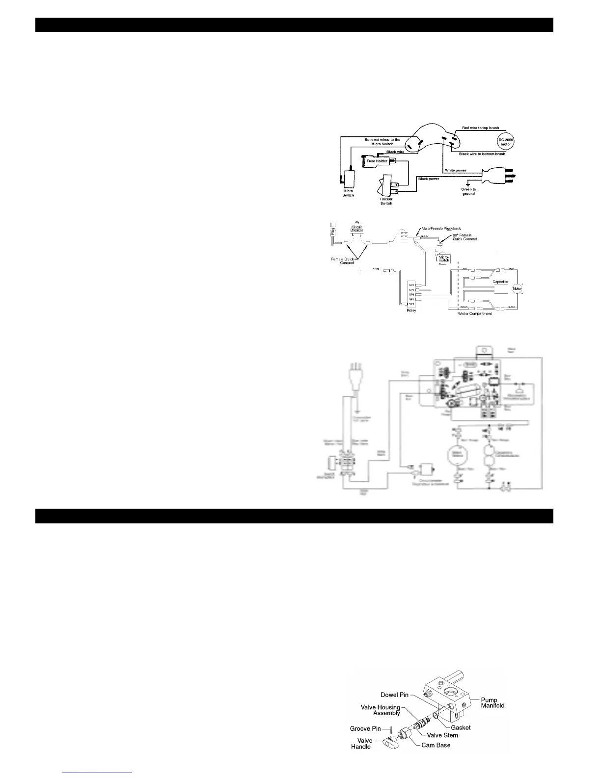
Wiring diagram, DC-2000
SERVICE (DC-3100)
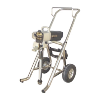
Wiring diagram, DC-3100
MAINTENANCE
Before proceeding, follow the Pressure Relief Procedure outlined
previously in this manual. Additionally, follow all other warnings to
reduce the risk of an injection injury, injury from moving parts or
electric shock. Always unplug the sprayer before servicing!
GENERAL REPAIR AND SERVICE NOTES
1) Before repairing any part of the sprayer, read the instructions
carefully, including all warnings. Never pull on a wire to disconnect
it. Pulling on a wire could loosen the connector from the wire.
2) Test your repair before regular operation of the sprayer to be sure
that the problem is corrected. If the sprayer does not operate
properly, review the repair procedure to determine if everything was
done correctly. Refer to the Troubleshooting section to help identify
other possible problems.
3) Make sure that the service area is well ventilated in case solvents
are used during cleaning. Always wear protective eyewear while
servicing. Additional protective equipment may be required depend-
ing on the type of cleaning solvent. Always contact the supplier of
solvents for recommendations.
4) If you have any further questions concerning your LEMMER Airless
Sprayer, call one of our locations listed in the back of this manual.
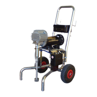
REPLACING THE PRIME/SPRAY VALVE
Perform the following procedure using PRIME/SPRAY valve replace-
ment kit P/N L045-862.
1) Drive the groove pin out of the valve handle.
2) Remove the valve handle and the cam base.
3) Using a wrench, loosen and remove the valve housing assembly
from the pump manifold.
4) Make sure the gasket is in place and thread the new valve housing
assembly into the pump manifold. Tighten securely with a wrench.
5) Place the cam base over the valve housing assembly.
Lubricate the cam base with grease and line up the cam with the pump
manifold using the dowel pin.
6) Line up the hole on the valve stem with the hole in the valve handle.
7) Insert the groove pin into the valve handle and through the valve
stem to secure the valve handle in position.
Wiring diagram, DC-3100N