16
SERVICE (DC-3100)
5) Slide the retaining ring up on the slider assembly to expose the
connecting pin.
6) Push the connecting pin forward through the slider assembly and
piston. The connecting pin will fall into a recessed area of the gear
box housing where it can be retrieved.
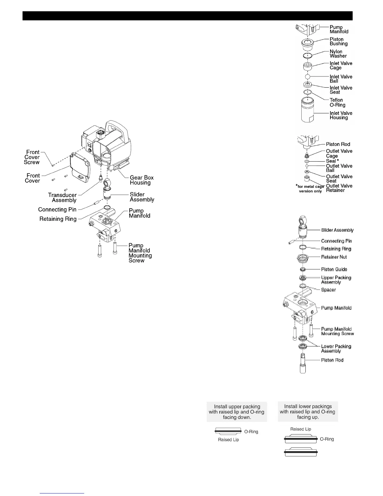
7) Using 3/8" a hex wrench, loosen and remove the two pump manifold
mounting screws.
8) Pull the pump manifold down off of the gear box housing.
9) Using a wrench, remove the transducer assembly from the pump
manifold.
10) Thread the new transducer assembly into the pump manifold.
Tighten securely with a wrench.
11) Reassemble the pump by reversing steps 1-8.
Make sure the transducer is aligned properly with the hole in the
pump manifold during reassembly. Improper alignment may cause
damage to the transducer o-ring.
SERVICING THE FLUID SECTION
Use the following procedures to service the valves and repack the fluid
section. Perform the following steps before performing any mainte-
nance on the fluid section.
1) Loosen and remove the four front cover screws. Remove the front
cover.
2) Position the slider assembly at the bottom, dead-center of its stroke
so that the connecting pin and retaining ring are visible below the
slider assembly. This is done by turning the sprayer on and off in
short bursts until the connecting pin is visible below the slider
housing.
3) Perform the Pressure Relief Procedure and unplug the sprayer.
Warning: before proceeding, follow the Pressure Relief Procedure
outlined previously in this manual. Additionally, follow all other
warnings to reduce the risk of an injection injury, injury from
moving parts or electric shock. Always unplug the sprayer before
servicing!
4) For Upright Cart units, remove the return hose from the hose clip on
the siphon tube. Unscrew the siphon tube from the inlet valve
housing.
5) For Low Boy cart units, remove the retaining ring from the bottom of
the inlet valve housing using a snap ring pliers. Remove the return
hose clamp and pull the return hose from its fitting on the pump
manifold. Remove the suction set assembly.
6) Loosen and remove the high-pressure hose from the outlet fitting on
pump manifold.
SERVICING THE VALVES
The design of the fluid section allows access
to the inlet valve and seat as well as the outlet
valve and seat without completely disassem-
bling the fluid section. It is possible that the
valves may not seat properly because of
debris stuck in the foot valve seat or outlet
valve seat. Use the following instructions to
clean the valves and reverse or replace the
seats.
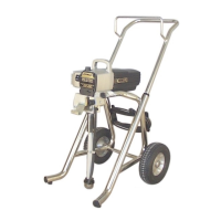
1) Using a wrench, loosen and remove the
inlet valve housing from the pump
manifold.
2) Clean out any debris in the inlet valve
housing and examine the valve housing
and seat. If the seat is damaged, reverse
or replace the seat.
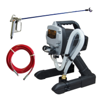
3) Using a 5/16" hex wrench, loosen and remove the outlet valve
retainer from the piston rod.
NOTE: Always service the outlet valve with
the piston rod attached to the pump. This
will prevent the piston rod from rotating
during disassembly of the outlet valve.
4) Clean out any debris and examine the
valve housing and seat. If the seat is
damaged, reverse or replace the seat.
5) Remove, clean, and inspect the outlet
valve cage and outlet valve ball. Replace
if they are worn or damaged.
6) Reassemble the valves by reversing the steps above. (Note: Seal
only req'd on DC3100N or units with metal outlet valve cage.)
REPACKING THE FLUID SECTION
1) Remove the inlet valve assembly
using the steps in the "Servicing the
Valves" procedure above.
NOTE: The outlet valve does not
need to be disassembled from the
piston rod for this procedure.
2) Slide the retaining ring up on the
slider assembly to expose the
connecting pin. (Step 2 & 3 not req'd
on DC3100N with slotted piston.)
3) Push the connecting pin forward
through the slider assembly and
piston. The connecting pin will fall
into a recessed area of the gear box
housing where it can be retrieved.
4) Using 3/8" a hex wrench, loosen
and remove the two pump manifold
mounting screws.
5) Pull the pump manifold down off of
the gear box housing.
6) Slide the piston rod out through the
bottom of the pump manifold.
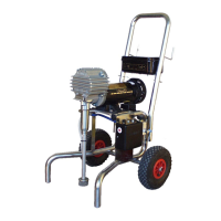
7) Loosen and remove the retainer nut
and piston guide from the pump
manifold.
8) Remove the upper and lower
packings from the pump manifold.
9) Clean the pump manifold and install the new upper and lower packings.
Refer to the illustration below for proper packing orientation.
10) Inspect the piston rod for wear and replace if necessary.
11) Insert the piston guide into the retainer nut. Thread the retainer nut
into the pump manifold until it is hand tight.