For other possible
orientations and advice on mounting the StabPLUS, see page 16 and the Reference Guide.
Because the Stabilizer PLUS uses accelerometers as well as gyros (so is
sometimes called a “6-axis” stabilizer), for best performance it should be
located reasonably close to the center of gravity of the model.
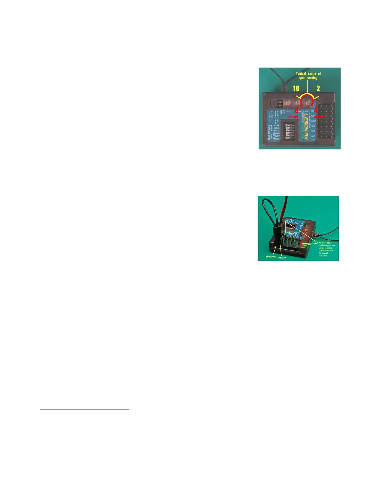
Check that the three gain pots are set to their mid-points – i.e., 12 o’clock
(straight up – see picture). This is the starting point for adjustment.
To gain familiarity with the StabPLUS, it’s a good idea to test bind the
stabilizer on the bench, without servos attached, before installing in the
model.
Binding
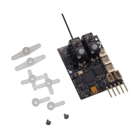
1. Insert a bind plug into the Bind/channel 7 slot.
2. With the transmitter turned OFF, apply power to the stabilizer. The Red and Green lights of Indicator 2
(and the Red internal light) should flash rapidly to indicate that stabilizer is in Bind Mode.
3. Turn ON the transmitter in Bind Mode (see the instructions for your transmitter). The transmitter
should be separated from the stabilizer by 1-2m (3-6 feet). In some cases,
even more separation may be needed for binding.
4. Wait until the transmitter indicates “bind complete” or the rapid
Red/Green flashing stops. If your bind process involves holding a button or
switch, hold for a couple of seconds more, then release.
5. Wait up to 20 seconds or so for the initialization process to complete, as
indicated by: Indicator 1 (Green/Blue) lights no longer flashing, Indicator 2
(Red/Green) lights signaling stabilizer mode (see below), and the
transmitter acquiring control of the servos.
6. Power down the stabilizer and transmitter. IMPORTANT: Don’t forget to remove the bind plug.
To test the bind, turn on the transmitter and then the stabilizer. Wait for initialization to complete. Verify
control of stabilization by placing the channel 5 (Gear) switch in each of its positions. A three-position
switch should cause the stabilizer to display the following:
Position 0: OFF – Red/Green solid (or flickering very slightly); no servo movement when model is rotated.
Position 1: Gyro – Green ON solid, Red OFF; servos move briefly when model is rotated.
Position 2: Autolevel – Red and Green lights flashing alternately; aileron and elevator servos stay
deflected when model is not level, rudder servo moves briefly when model is rotated (yawed).
With a two-position switch for channel 5, only OFF and Autolevel mode will be available by default. This can
be changed to OFF and Gyro, as explained under Changing Mode Order (see page 14).