Page 16
HORIZONTAL APPLICATION
IMPORTANT
When removing the coil, there is possible danger of
equipment damage and personal injury. Be careful when
removing the coil assembly from a unit installed in right-
or left-hand applications. The coil may tip into the drain
pan once it is clear of the cabinet. Support the coil when
removing it.
WEIV DNEWEIV TNORF
ANGLE IRON OR SHEET
METAL
E
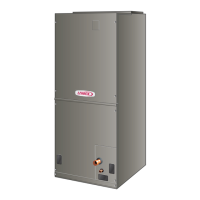
ANCE 4 IN. (102 MM)
MAXIMUM 1/2”
LONG SCREW
AIR FLOW
FIGURE 12. Suspend Horizontal Unit
NOTE – When the unit is installed in horizontal applica-
tions, a secondary drain pan is recommended. Refer to
local codes.
NOTE – This unit may be installed in left- or right-hand air
discharge horizontal applications. Adequate support must
be provided to ensure cabinet integrity. Ensure that there
is adequate room to remove service and access panels if
installing in the horizontal position.
LEFT-HAND DISCHARGE
For horizontal left-hand air discharge, the following eld
modications are required. Reference sticker is located on
coil top plate.
1 - Remove access panels and the corrugated padding
between the blower and coil assembly. Discard the
corrugated padding.
2 - Pull the coil assembly from unit. Pull o the
horizontal drain pan.
3 - Remove the drain plugs from back drain holes on
horizontal drain pan and reinstall them on front holes.
IMPORTANT
After removal of drain pan plug(s), check drain hole(s)
to verify that drain opening is fully open and free of any
debris. Also check to make sure that no debris has fallen
into the drain pan during installation that may plug up the
drain opening.
4 - Rotate drain pan 180º front-to-back and install it on
the opposite side of the coil.
5 - Remove screws from top cap.
6 - Remove plastic plug from left hole on coil front end
seal and reinstall plug in back hole.
90º
BEND
CABINET
SUPPORT
COIL SHOWN IN UPLOAD POSITION FOR EASY CONVERSION
TOP CAP SCREWS
DRAIN PAN
INSTALLED
HERE
DRAIN PAN
SHIPPING
LOCATION
TOP CAP ROTATED TO
CORRECT POSITION
———— DRAIN PLUGS ————
REINSTALLED HERE REMOVED FROM HERE
BACK COIL END SEAL
TOP
CAP
90º
BEND
ALIGN HOLES WITH
HOLES IN COIL END
PLATE. STARTING WITH
THE ROUND HOLES ON
THIS END.
FIGURE 13. Field Modication for
Left-Hand Discharge
7 - Rotate top cap 180º front-to-back and align with
unused screw holes. Holes must align with front
and back coil end plates. The top cap has a 45º
bend on one side and a 90º bend on the other.
The 90º bend must be on the same side as the
horizontal drain pan as illustrated in gure 13.
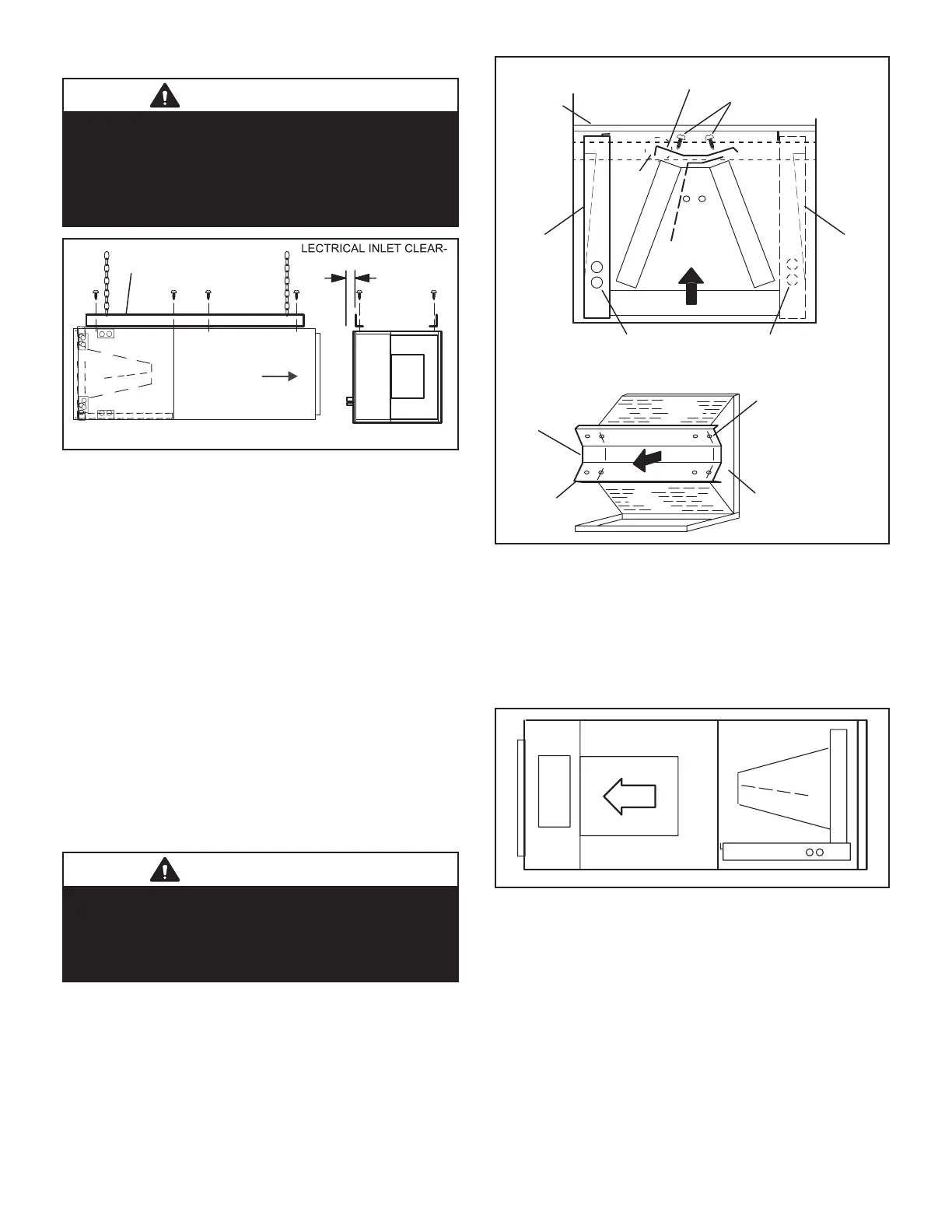
FIGURE 14. Left-Hand Discharge Conguration
NOTE – Be very careful when reinstalling the screws into
the coil end plate engaging holes. Misaligned screws may
damage the coil.
8 - From the upow position, ip cabinet 90º to the left
and set into place. Replace blower assembly. See
gure 14 for orientation.
9 - Knock out drain seal plate from access door. Secure
plate to cabinet front ange with screw provided.
 Loading...


