Page 20
Installing the Condensate Drain
IMPORTANT
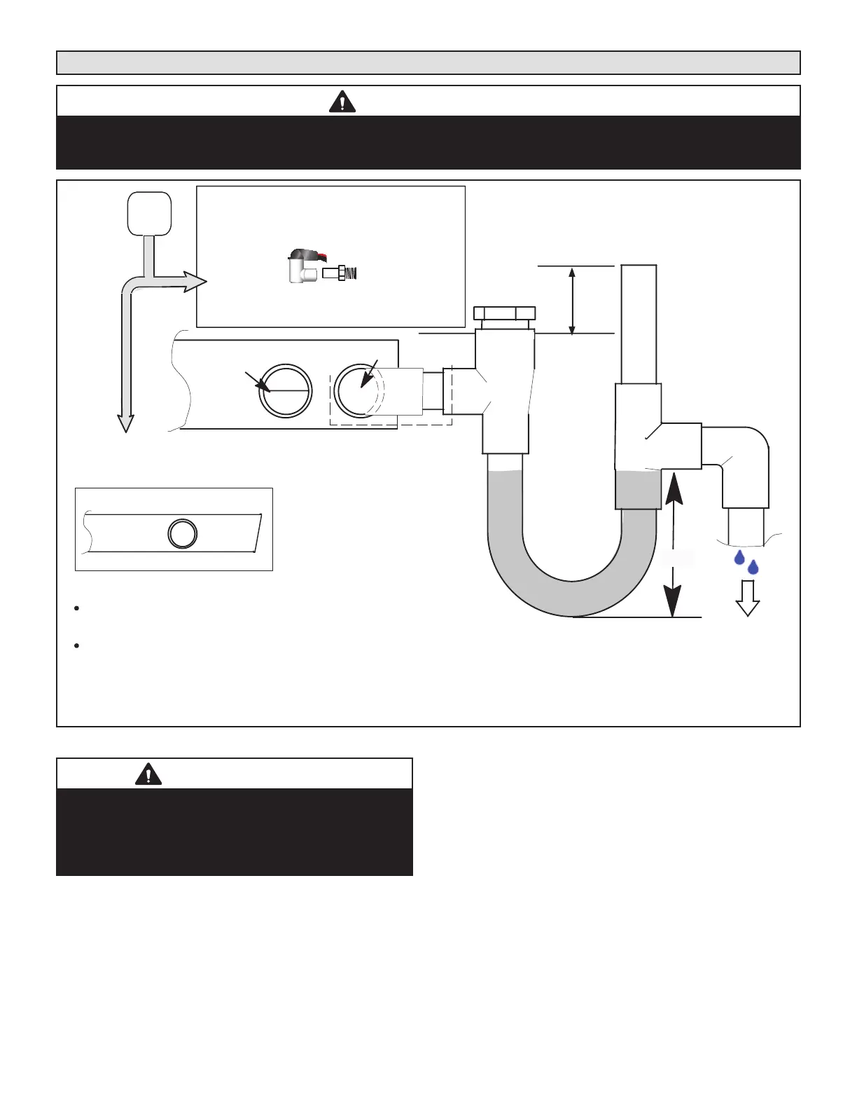
On units of this type, where the blower “draws” rather than “blows” air through the coil, traps must be installed in the
condensate drain lines (primary and auxiliary, if used). Traps prevent the blower from drawing air through the drain lines
into the air supply.
ABOVE
FINISHED
SPACE?
OVERFLOW DRAIN LINE
ALWAYS RUN AN OVERFLOW DRAIN LINE. IF NOT POSSIBLE TO
ROUTE OVERFLOW DRAIN LINE, INSTALL LOW VOLTAGE
OVERFLOW SWITCH KIT. WIRE KIT TO SHUT DOWN
COMPRESSOR PER INSTRUCTIONS.
NO
YES
LENNOX #
X3169
CLEAN OUT
VENT
PRESS IN
(DO NOT GLUE)
VENT MUST EXTEND
ABOVE HEIGHT OF
COIL DRAIN PAN BY
TWO INCHES (51MM)
1” X 3/4” X 3/4”
REDUCING
TEE WITH
PLUG
LENNOX
1
P-TRAP
49P66, J-TRAP #
91P90 OR ANY
PVC SCH 40 P- OR
J-TRAP 3/4”
OVERFLOW
DRAIN
AIR HANDLER DRAIN PAN
WHEN A COIL IS LOCATED ABOVE A FINISHED SPACE, A
3/4” (19.1MM) SECONDARY DRAIN LINE MUST BE:
CONNECTED TO SECONDARY DRAIN PAN
OR
CONNECTED TO THE OVERFLOW DRAIN OUTLET OF
THE AIR HANDLER DRAIN PAN.
TRAPS MUST BE DEEP ENOUGH TO OFFSET MAXIMUM STATIC DIFFERENCES —
GENERALLY, TWO INCHES (51MM).
DRAIN LINE SHOULD
SLOPE A MINIMUM OF
ONE INCH PER 10
FEET (25MM PER 3
METERS)
NOTE — WHEN A AIR HANDLER IS LOCATED
ABOVE A FINISHED SPACE THE SECONDARY
DRAIN PAN MUST HAVE A LARGER FOOTPRINT
THAN THE AIR HANDLER.
MAIN
DRAIN
TO APPROVED
DRAIN
FOR NEGATIVE PRESSURE COILS (BLOWER
AFTER COIL) TRAPS ARE REQUIRED ON ALL
DRAIN LINES CONNECTED TO COIL.
COMPACT OVERFLOW SWITCH WITH 3/4” FEMALE SLIP INLET
AND MALE ADAPTER, TWO PART DESIGN FOR USE WHERE
OBSTRUCTIONS PREVENT DIRECT THREADING
SECONDARY
DRAIN PAN
2”
(51MM)
TRAP DEPTH
1
LENNOX P-TRAP 49P66 REQUIRES A LARGER INSTALLATION SPACE THAN THE J-TRAP 91P90.
2
PIPE NIPPLE PROVIDED IN BAG ASSEMBLY - SCH 80, 3/4” I. D. X 5” - 34K7401 (1): CUT THE PIPE IN HALF AND USE IT TO ROUTE THE MAIN DRAIN.
FIGURE 18. Typical Main and Overow Drain Installations
IMPORTANT
After removal of drain pan plug(s), check drain hole(s)
to verify that drain opening is fully open and free of any
debris. Also check to make sure that no debris has fallen
into the drain pan during installation that may plug up the
drain opening.
1 - Remove the appropriate drain knockouts. If
necessary, remove the indoor coil assembly from
the cabinet.
2 - Connect primary drain line connection to the primary
drain pan connection. The primary drain connection
is ush with the bottom of the inside of the pan.
Secondary connection is raised above the bottom
of the inside of the pan.
NOTE – When making drain tting connections to the
drain pan, hand tighten the tting and use a thread seal-
ant. Over-tightening the ttings can split connections on
the drain pan.
3 - If the auxiliary drain line is to be used, remove
the plug and route the drain line so that water
draining from the outlet will be easily noticed by
the homeowner. The auxiliary drain line does not
require venting or a trap. Refer to local codes.
4 - After removal of drain pan plugs, check the drain
port to see if holes have been drilled. If not drilled,
use a 19/32” bit to drill out the primary drain hole;
use a 3/8” drill bit for the secondary drain hole.
Remove all drill shavings.
5 - Make sure drain ports and drain pan are free of all
debris.
 Loading...


