Page 17
10 - Flip access door and replace it on the unit.
11 - Set unit so that it is sloped toward the drain pan end
of the unit. See sloping section gure 17. Connect
return and supply air plenums as required using
sheet metal screws.
12 - If suspending the unit, it must be supported along the
entire length of the cabinet. If using chain or strap,
use a piece of angle iron or sheet metal attached to
the unit (either above or below) so that the full length
of the cabinet is supported. Use securing screws no
longer than 1/2ʺ to avoid damage to coil or lter, as
illustrated in gure 12. Connect return and supply
air plenums as required using sheet metal screws.
RIGHT-HAND DISCHARGE
1 - Determine which plugs are required for drain line
connections.
2 - With access door removed, remove drain line plugs
to install drain lines.
3 - Set unit so that it is sloped toward the upow drain
pan end of the unit and level from front to back of
unit (see gure 15).
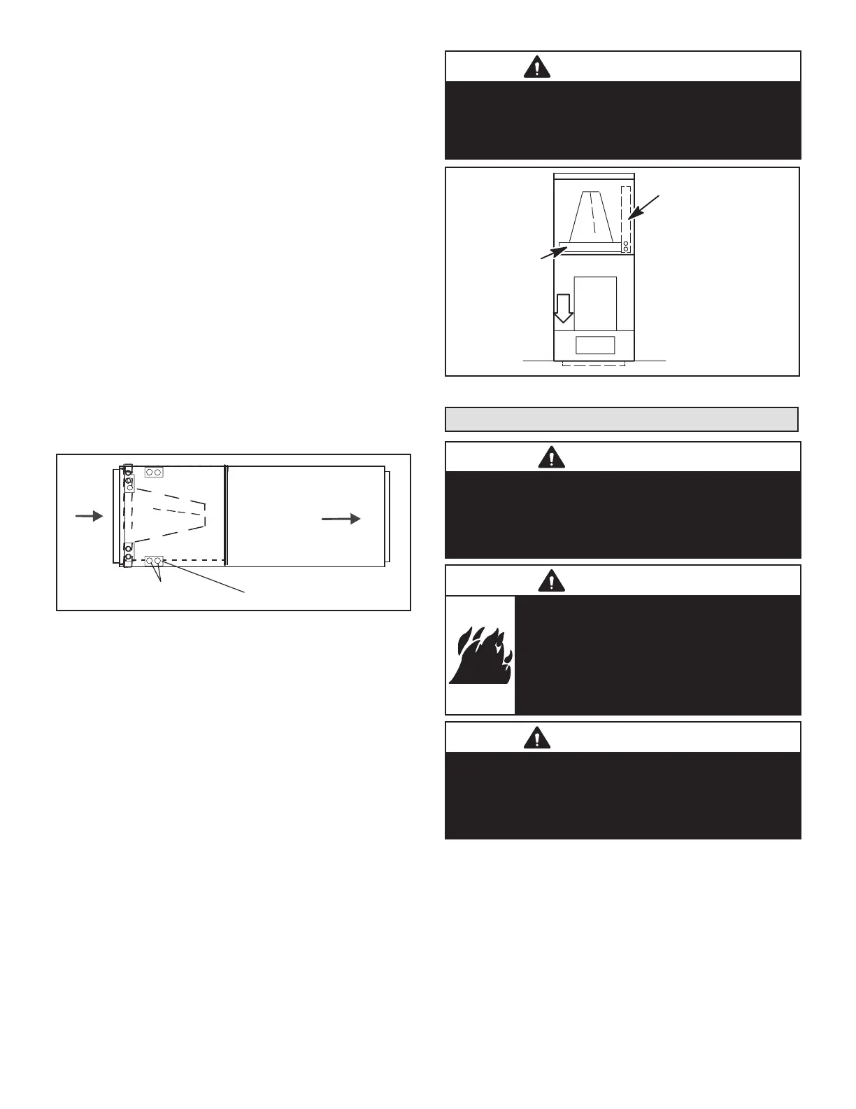
4 - The horizontal conguration is shown in gure 15.
Drains
AIR FLOW
PLUGS
RIGHT‐HAND DRAINS
FIGURE 15. Right-Hand Discharge Conguration
5 - If the unit is suspended, the entire length of the
cabinet must be supported. If you use a chain or
strap, use a piece of angle iron or sheet metal
attached to the unit (either above or below) to
support the length of the cabinet. Use securing
screws no longer than 1/2 inch to avoid damaging
the coil or lter. See gure 12. Use sheet metal
screws to connect the return and supply air plenums
as required.
DOWNFLOW APPLICATION
NOTE – If downow application is required, separately or-
der kit number Y9658 (-024 through -030) or Y9659 (-036
through -042) .Use the installation instruction 507797-01
provided with the downow kit. Also use metal or class I
supply and return air plenums. Figure 16 shows proper
orientation.
IMPORTANT
If electric heat section with circuit breakers (ECBA25) is
installed in a CBA25UHE unit in a downow application,
the circuit breakers must be rotated 180° to the UP
position. See ECBA25 installation instructions for more
details.
HORIZONTA L DRAIN PAN
(REMOVE FROM UNIT)
UPFLOW /
DOWNFLOW
DRAIN PAN
FIGURE 16. Downow Discharge Position
Brazing Connections
WARNING
Polyol ester (POE) oils used with HFC-410A refrigerant
absorb moisture very quickly. It is very important that the
refrigerant system be kept closed as much as possible.
DO NOT remove line set caps or service valve stub caps
until you are ready to make connections.
WARNING
Danger of re. Bleeding the refrigerant
charge from only the high side may result
in pressurization of the low side shell and
suction tubing. Application of a brazing torch
to a pressurized system may result in ignition
of the refrigerant and oil mixture. Check the
high and low pressures before applying heat.
IMPORTANT
To prevent the build-up of high levels of nitrogen when
purging, it must be done in a well-ventilated area. Purge
low-pressure nitrogen (1 to 2 psig) through the refrigerant
piping during brazing. This will help to prevent oxidation
and the introduction of moisture into the system.
 Loading...


