Page 8
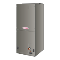
UPFLOW DRAIN PAN
EXPANSION VALVE
COIL
BLOWER COMPARTMENT
CONTROL BOX
ELECTRIC HEAT
FIGURE 1. Typical Unit Parts Arrangement
Application
All major blower coil components must be matched ac-
cording to Lennox recommendations for the unit to be
covered under warranty. Refer to the Product Specica-
tion bulletin for approved system matchups. A misapplied
system will cause erratic operation and can result in early
unit failure.
The units come with factory installed check and expan-
sion valve for all applications. The TXV valve has been
installed internally for a cleaner installation and is acces-
sible if required.
Unit Components
CONTROL BOX
The CBA25UHE control box is located above the blower
section shown in gure 1. Line voltage and electric heat
connections are made in the control box. Optional electric
heat ts through an opening located in the center of the
control box. When electric heat is not used, cover plates
cover the opening. The electric heat control arrangement
is detailed in the electric heat section of this manual.
TRANSFORMER
All CBA25UHE series units use a single line voltage to
24VAC transformer mounted in the control box. The
transformer supplies power to the control circuits in the
indoor and outdoor unit. Transformers are rated at 40VA.
208/240VAC single phase transformers use two primary
voltage taps as shown in gure 2.
BLUE
ORANGE
RED
240 VOLTS
208 VOLTS
PRIMARY
SECONDARY
FIGURE 2. 208 / 240 Volt Transformer
BLOWER MOTOR (B3)
CBA25UHE-024, -030, -036 and -042 units use single-phase
direct drive constant torque blower motors. Figure 3 shows
the parts arrangement. All motors have ve speed taps. Typ-
ically, speed tap #3 is energized during normal operation.
All units are factory wired for heat pump and cooling ap-
plications with or without electric heat. The unit wiring dia-
grams will provide factory set blower speeds.
See motor detail section on page 28.
Motor Terminals
FIGURE 3. Blower Assembly
COIL
CBA25UHE units have dual slab coils arranged in an A
conguration. Each coil has two or three rows of aluminum
tubes tted with ripple-edged aluminum ns. An expansion
valve feeds multiple parallel circuits through the coils. The
coil is designed to easily slide out of the unit cabinet.
PLASTIC DRAIN PANS
Drain pans are provided and installed on the CBA25UHE.
The drain pans are made from berglass lled plastic.
 Loading...


