Page 26
Sequence of Operation
Cooling (Cooling Only or Heat Pump)
On all models, the 24 volt line will go directly to the termi-
nal board from the transformer. The normally open con-
tacts close, causing the indoor blower motor to operate;
depending on the indoor blower motor, there may be a
delay. The circuit between R and Y is completed, closing
the circuit to the contactor in the outdoor unit, starting the
compressor and outdoor fan motor.
On heat pumps, circuit R and O energizes the reversing
valve, switching the valve to the cooling position. (The re-
versing valve remains energized as long as the thermo-
stat selector switch is in the COOL position.)
At the completion of the cooling demand, the indoor blow-
er and outdoor unit should cycle o. Air handler should
cycle o 45 seconds after the outdoor unit shuts o.
Heating (Electric Heat Only)
When the thermostat calls for heat, the circuit between R
and W is completed, and the heat sequencer is energized.
A time delay follows before the heating elements and the
indoor blower motor come on. Units with a second heat
sequencer can be connected with the rst sequencer to W
on the thermostat sub-base, or they may also be connect-
ed to a second stage on the sub-base.
Heating (Heat Pump)
On all models, the 24 volt line will go directly to the termi-
nal board from the transformer. The normally open con-
tacts close, causing the indoor blower motor to operate;
depending on the indoor blower motor, there may be a
delay. The circuit between R and Y is completed, closing
the circuit to the contactor in the outdoor unit, starting the
compressor and outdoor fan motor.
If the room temperature continues to decrease, the cir-
cuit between R and W1 is completed by the second-stage
heat room thermostat. Circuit R-W1 energizes a heat se-
quencer. The completed circuit will energize supplemen-
tal electric heat (if applicable). Units with a second heat
sequencer can be connected with the rst sequencer to
W1 on the thermostat. They may also be connected to
a second heating stage W2 on the thermostat sub-base.
Emergency Heat (Heating Heat Pump)
If the selector switch on the thermostat is set to the emer-
gency heat position, the heat pump will be locked out of
the heating circuit, and all heating will be electric heat (if
applicable). A jumper should be placed between W2 and E
on the thermostat sub-base so that the electric heat con-
trol will transfer to the rst-stage heat on the thermostat.
This will allow the indoor blower to cycle on and o with
the electric heat when the fan switch is in the AUTO po-
sition.
Constant Torque Speed Blower Motor
(ECM) (B3)
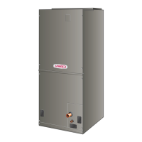
Blower Motor (B3)
To Remove Blower From Unit: Remove wiring jack plug and
three screws and slide blower out.
TYPICAL BLOWER MOTOR
(B3) REMOVAL
FIGURE 22
The constant torque ECM (electronically commutated mo-
tor) communicates with the air handler control via 24VAC
inputs. It is programmed to provide a constant level of
torque (current / power) to the motor. This is a multi-tap
motor with the ability to have 1 to 5 programmed levels of
torque (see table 4). Each value equals a specic amount
of torque to create the proper amount of airow for each
system demand. This value is specic to model and size
of system.
Each tap can have a unique amount of torque programmed
for a specic purpose. For example, switching from Tap 1
to Tap 2 may increase the airow, but not necessarily at
a specic interval like changing from low to medium low
speed on a PSC motor.
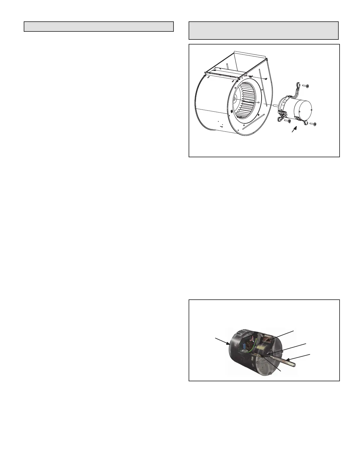
Internal components are shown in gure 23. The stator
windings are split into three poles which are electrically
connected to the controller. This arrangement allows mo-
tor windings to turn on and o in sequence by the control-
ler.
STATOR
(WINDINGS)
OUTPUT
SHAFT
BEARING
ROTOR
CONTROLLER
BLOWER MOTOR COMPONENTS
FIGURE 23
 Loading...


