Page 27
The controller uses sensing devices to sense what posi-
tion the rotor is in at any given time. By sensing the posi-
tion of the rotor and then switching the motor windings on
and o in sequence, the rotor shaft turns the blower.
Operation
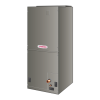
The 230VAC voltage connections to the motor are labeled
L, G and N.
• 230VAC L = L1 115VAC, G = Ground, N = L2 115VAC
The 230VAC is connected to the motor at all times. This
voltage operates the internal electronics and drives the
motor. In addition, the motor requires a low voltage to op-
erate. The low voltage to the motor is delivered to taps
1-5 and the (C) terminal from the control relay. The mo-
tor accepts a communication signal of 24VAC on these
taps. Instead of energizing a motor speed (winding) on a
PSC motor for each demand (heat cool, constant fan); the
communication voltage directs the motor to operate at the
torque value stored for each tap.
VOLTAGE CONNECTIONS
FIGURE 24
During each demand, the fan motor will maintain the se-
lected torque during changes in the systems external stat-
ic pressure (ESP) (constant torque). If ESP increases the
motor will use more power (current) to maintain torque.
The motor has a programmed limit of operation to protect
itself from damage, due to the energy it must use to main-
tain torque at high external static pressures. If the systems
maximum total ESP is exceeded, torque will not be main-
tained, however the motor will deliver as much torque as
possible, without causing damage to itself.
Constant torque allows the fan motor to maintain the torque
(current) delivered to the motor when ESP is higher than
recommended and/or changes during system operation.
ESP (the resistance to the movement of air) is increased
when duct work is undersized, poorly constructed and/or
full or dirt or debris. ESP can increase during system op-
eration when dirt builds up on the air distribution systems
components, especially the lter, and when customers
close or block grilles and registers. When torque is main-
tained, airow does not decrease as fast as it would on a
PSC motor system. This decreases the eect ESP has on
loss of airow, providing better system performance and
eciency within the limits of the motor design.
The fan motor has no programmable (On) delays but mul-
tiple (O) delays are programmed into the motor. The o
delay is programmed into the motor and can not be ad-
justed.
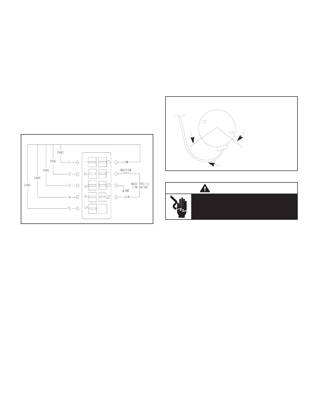
Installation
It is recommended that the electrical connections on the
ECM be facing down or between the 4 and 8 O-clock po-
sition, and a drip loop formed out of the wiring harness
leaving the motor. This is to prevent any moisture or water
that may get into the motor area from running into the con-
nectors where it could cause damage to the control. See
gure 25.
DRIP LOOP
BACK OF
UNIT
CONNECTOR
ORIENTATION (BETWEEN
4 AND 8 O'CLOCK)
DRIP LOOP
FIGURE 25
WARNING
Disconnect power from unit and wait at least
ve minutes to allow capacitors to discharge
before attempting to service motor. Failure to
wait may cause personal injury or death.
INDOOR BLOWER MOTOR (B3) CONTROL TROUBLE-
SHOOTING
Before troubleshooting any HVAC system, it is a good
practice to become familiar with the components and wir-
ing diagram. On fan motor systems it is a good practice to
check the tap selections and delay settings.
If the motor is running but the system is noisy, shutting
down on its limits or safeties or the evaporator coil is freez-
ing, there is a good chance the motor is good. The prob-
lem is most likely external to the motor.
• Check the tap selections using the HVAC OEM guide.
• Check the air distribution system components for dirt
load and closed dampers, registers and grilles.
• Measure the total external static pressure. Make repair(s)
if above the recommended maximum level and conrm
airow at the new total ESP with the air ow tables (be-
ginning on page 6). Aftermarket lter sizing is a com-
mon issue.
 Loading...


