Page 36 MUL41E-0610/06-2011
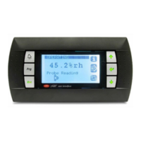
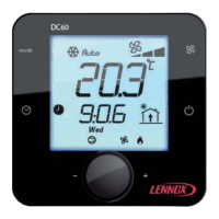
22 - DISPLAY DC60
22.1 - Function
The DC60 display is customized for the user to show a global operating overview of the unit and allow access to
some settings. In case of remote display, the cable length should not exceed 30m.
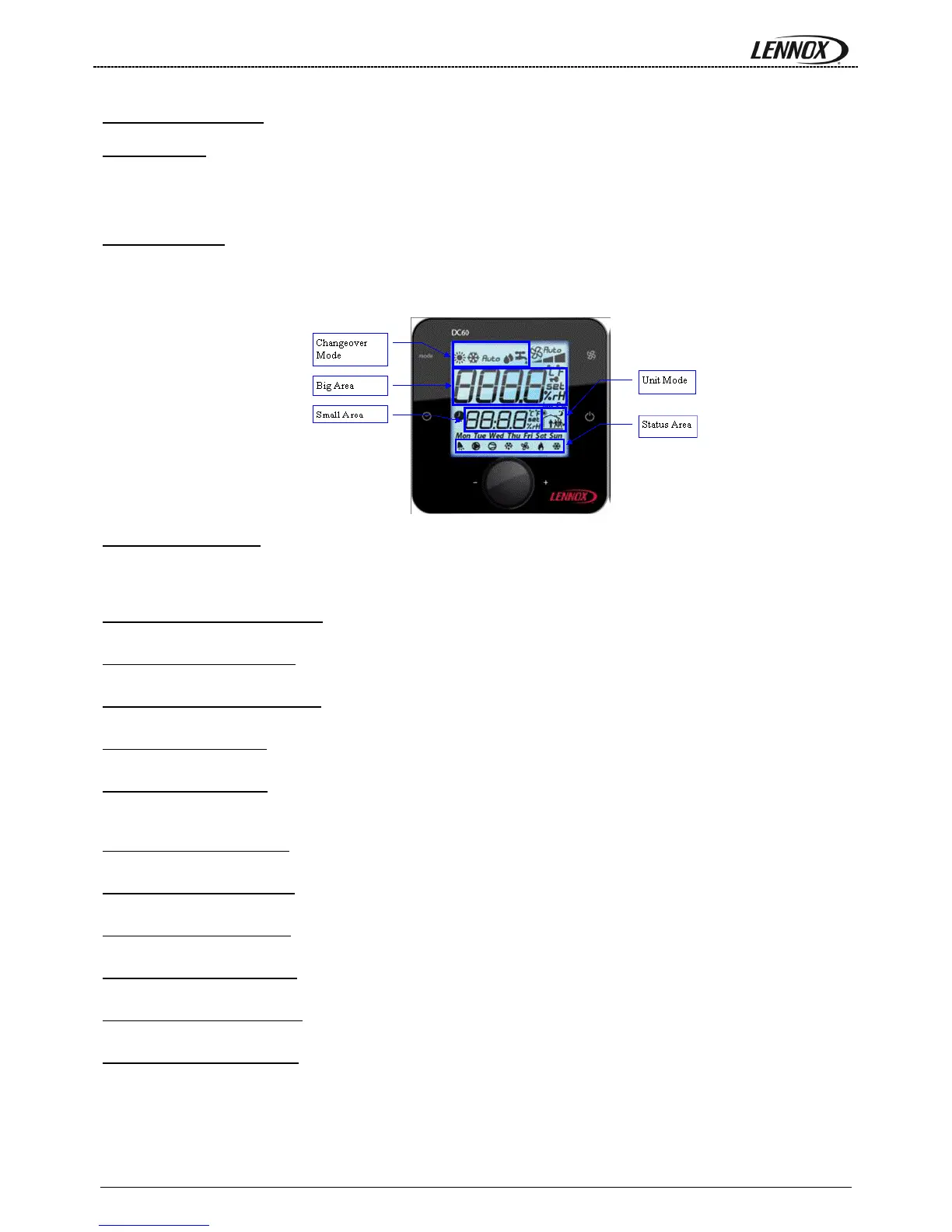
22.2 - Description
The DC60 terminal displays various status of the unit and offers the possibility to override the initial operating of the
unit. Use the wheel button to display the data desired in the big area. The small area specifies the type of the data
displayed.
22.2.1 - Set point “SET”:
Specify the evaporator water set point calculated by the CLIMATIC™ 60. The set point can be modified directly
by the DC60. Note that the select value will be automatically overwritten by the CLIMATIC™ 60 when the actual
zone will change (Z0Z6) if a scheduling has been defined.
22.2.2 - Outlet temperature “OUT”:
Specify the evaporator water outlet temperature.
22.2.3 - Inlet temperature “IN”
Specify the evaporator water inlet temperature.
22.2.4 - Outside temperature “Air”
Specify the outside air temperature.
22.2.5 - Alarm code “AL-”
Specify the alarm(s) code(s) active.
22.2.6 - Alarm clear “CL-”
Specify the alarm reset set point. To reset the active alarms, press the wheel button and set to 1 to active the
reset. The setting is automatically cleared by the CLIMATIC™ 60.
22.2.7 - Low pressure “LP-1”
Specify the low pressure of the circuit 1.
22.2.8 - High pressure “HP-1”
Specify the high pressure of the circuit 1.
22.2.9 - Superheating “SH-1”
Specify the superheating temperature of the circuit 1.
22.2.10 - Low pressure “LP-2”
Specify the low pressure of the circuit 2.
22.2.11 - High pressure “HP-2”
Specify the high pressure of the circuit 2.
22.2.12 - Superheating “SH-2”
Specify the superheating temperature of the circuit 2.
 Loading...