-00
58
KP07 VDU CONSOLE
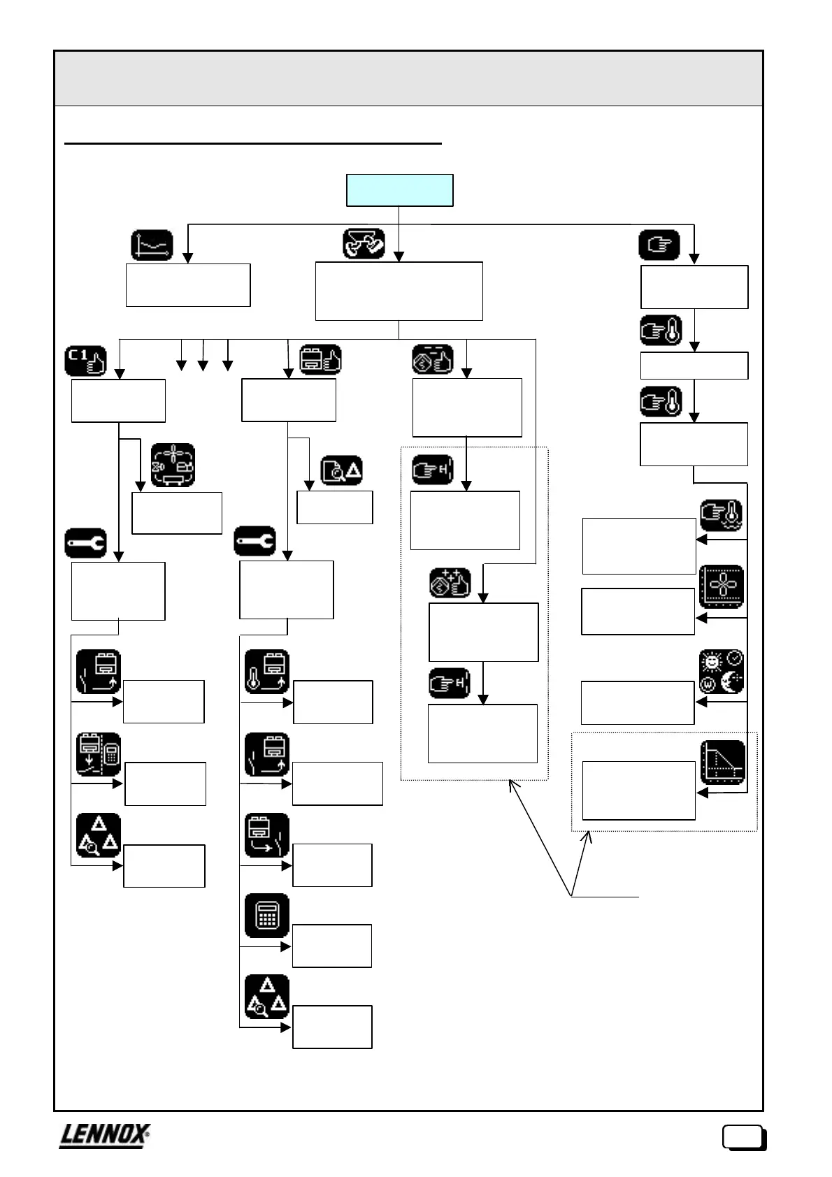
V. GENERAL TREE STRUCTURE OF SCREENS
For units with more than one refrigeration circuit, branches C2, C3 and C4, corresponding to operating states
for circuits 2, 3 and 4 respectively, are active.
Operating state
of the unit
Summary
Water temperature
curve
Access to operating states
of the circuits, machine and
pumps
Access to
machines
variables
Fault log
Analogue
inputs
Logic inputs
Variables
diverses
TOR
outputs
Compteurs
de pannes
Logic inputs
TOR/other
outputs
Fault
counters
Operating state
Circuit 1
Access to
circuit
variables
Refrigeration
circuit
Water
temperature
setting
Fan control
parameters
On/Off switches
for circuits
Password
Access to
settings
Operating state –
Chilled water
pumps
On/Off switches
of chilled water
pumps
Operating state –
Hot water pumps
On/Off switches –
Hot water pumps
C2 C3 C4
Options
Parameters for
regulation with
gradient
Idle time clocks
 Loading...

