SVL3
SVL1
DS
HP1
HP2
CH1
CH3
OS
LPT1
LPT1
HPT1
HPT2
LPT2
LPT2
HPT1
HPT2
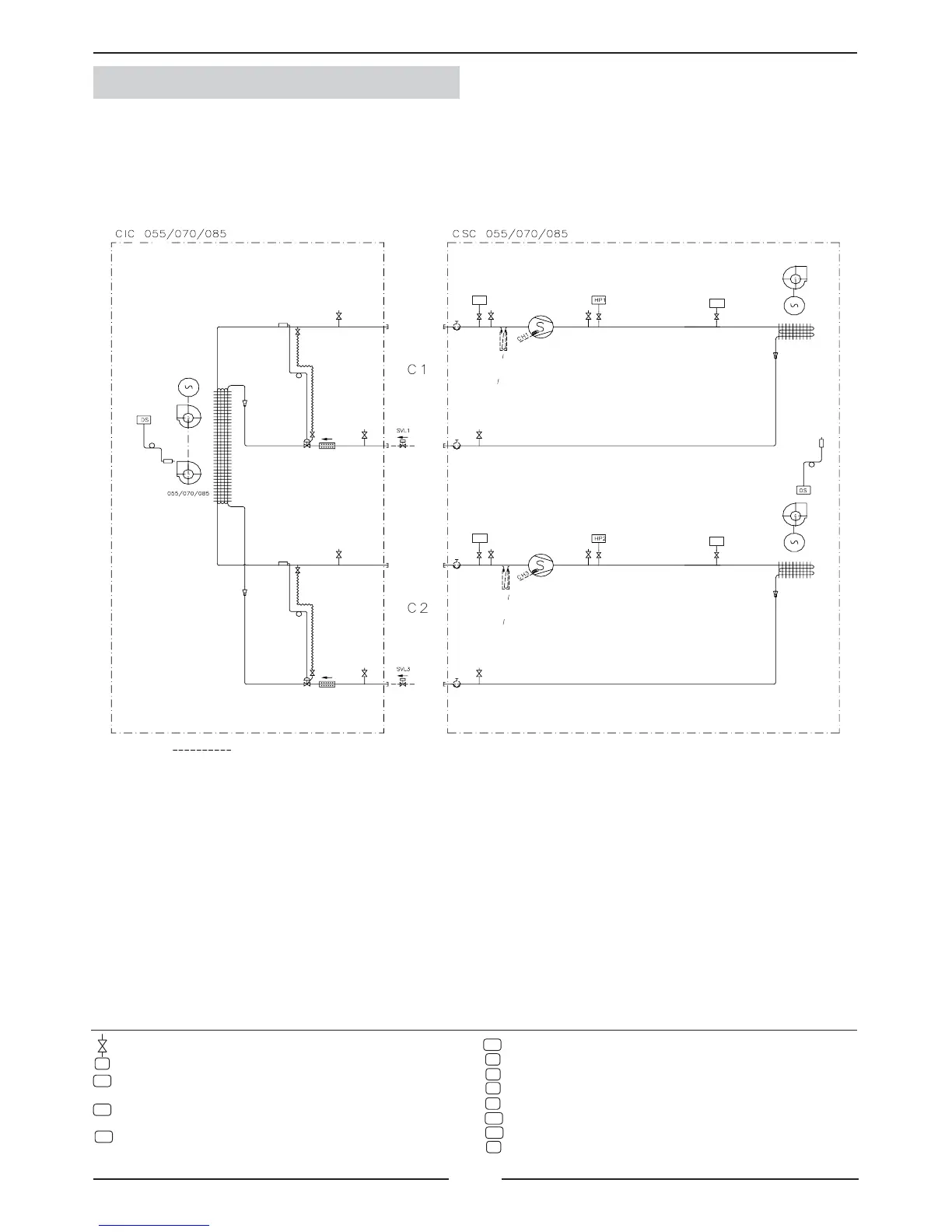
1.- GENERAL CHARACTERISTICS
1.5.- PIPING DRAWINGS COOLING ONLY UNITS
INDOOR UNIT
OUTDOOR UNIT
Scroll compressor
Scroll compressor
Fan
Coil
Expansion valve
Expansion valve
Filter drier
Filter drier
Service valve
option
Suction accumulator
(Long distance connection option).
Suction accumulator
(Long distance connection option).
Fan motor
Coil
Fan motor
Coil
Service valve
option
Service valve
option
Service valve
option
Pressure gauge. (5/16” to be tted by the installer).
Discharge sensor.
Liquid solenoid valve. (Long distance option).
To be connected by the installer to indoor units.
Liquid solenoid valve. (Long distance option).
To be connected by the installer to indoor units.
Low pressure transducer, circuit 1.
Low pressure transducer, circuit 2.
High pressure switch, circuit 1.
High pressure switch, circuit 2.
Crank case heater. (Low ambient 0ºC or -15ºC option).
Crank case heater. (Low ambient 0ºC or -15ºC option).
High pressure transducer, circuit 1
High pressure transducer, circuit 2.
Outdoor temperature sensor
OPTION ELEMENT