• 10 •
SVL1
DS
SVL2
SVL3
(ELEMENTO OPCIONAL)
SVL3 SVL4
055/070/085
DS
LP2
SVL1
HP2
SVL2
PT2
LP1 HP1 PT1
C
H
3
C
H1
C2
C1
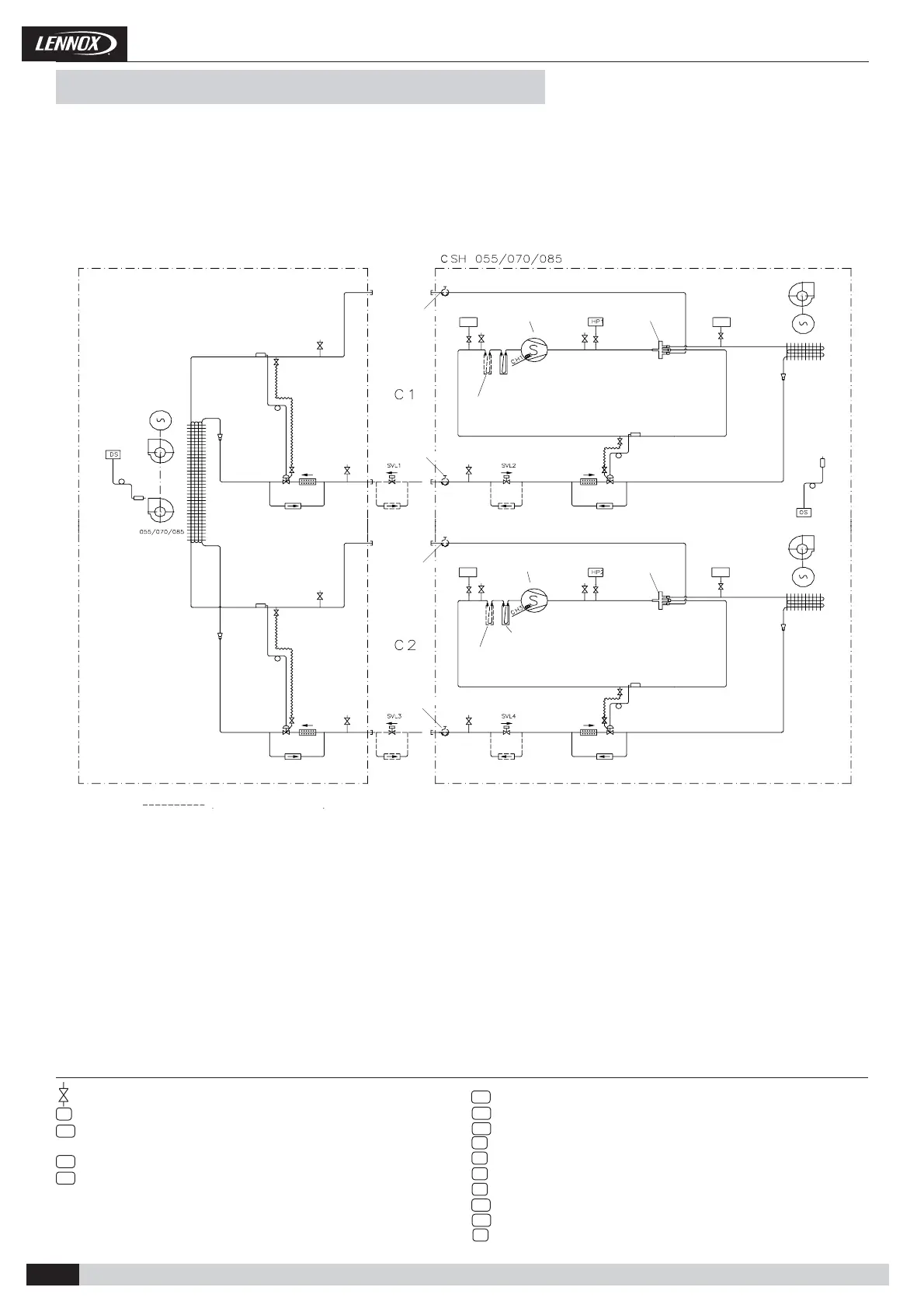
CSH 055/070/085
OS
HPT1LPT1
HPT2LPT2
HP1
HP2
CH3
CH1
SVL4
OS
HPT1
HPT2
LPT1
LPT2
Installation, Operation and Maintenance manual • CSC/CSH-MIL153E-1217-05/2018
1.- GENERAL CHARACTERISTICS
AIR TREATMENT UNIT. EXAMPLE
CONDENSING UNIT
Scroll compressor
4-way valve
Scroll compressor
4-way valve
OPTION ELEMENT
Coil
Fan motor
Coil
Fan
Expansion valve
Filter drier
Service valve option
Service valve option
Suction accumulator (Long
distance connection option)
Check valve Check valve
Filter drier
Expansion valve
Check valve
Suction accumulator
Check valve
Service valve option
Service valve option
Expansion valve
Filter drier
Suction accumulator (Long
distance connection option)
Check valve Check valve
Filter drier
Expansion valve
Check valve
Suction accumulator
Check valve
Pressure gauge. (5/16” to be fi tted by the installer).
Discharge sensor.
Liquid solenoid valve (Long distance option).
To be connected by the installer in the air treatment unit.
Liquid solenoid valve (Long distance option).
Liquid solenoid valve (Long distance option).
To be connected by the installer in the air treatment unit.
Liquid solenoid valve (Long distance option).
Low pressure transducer circuit 1.
Low pressure transducer, circuit 2.
High pressure switch, circuit 1.
High pressure switch, circuit 2.
Crank case heater.
Crank case heater.
High pressure transducer, circuit 1.
High pressure transducer, circuit 2.
Outdoor temperature sensor.
Fan motor
Coil
1.5.- PIPING DRAWINGS HEAT PUMP UNITS