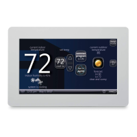
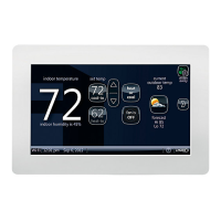
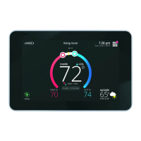
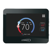
icomfort Touch Screen 7−Day Programmable Thermostat
Page 29
Parameter Name NoteDependency
Value
Parameter Name NoteDependency
Incr.Max.Min.Default
Cooling Airflow Setting
High Cooling Airflow
(CFM @ 100% cool)
OU tons (OUNC) *
400CFM
Min CFM Max CFM 25 Outdoor Unit present 1/2 HP blower
Min CFM Max CFM 25 1 HP blower
Low Cooling Airflow
(CFM @ lowest cool stage)
See Note1 below Min CFM Max CFM 25 2+ stage Outdoor Unit present 1/2 HP blower
Min CFM Max CFM 25 1 HP blower
Airflow Profile − Cooling DIP SW 0 3 1 Outdoor Unit present 0–Text ID 0x0105
(A:ON:50%/30s,82%/7.5min
OFF:50%/30s)
1–Text ID 0x0106 (B:ON:82%/7.5min;
OFF: No delays)
2–Text ID 0x0107 (C:ON: No delays;
OFF: 45sec delay)
3–Text ID 0x0108 (D:No delays)
Heat Pump Airflow Setting
High Heat Pump Airflow (CFM @
100%)
OU tons (OUNC) *
400CFM
Min CFM Max CFM 25 Heat Pump present 1/2 HP blower
Min CFM Max CFM 25 1 HP blower
Low Heat Pump Airflow (CFM @ lowest
stage)
See Note 2 below Min CFM Max CFM 25 2+ stage Heat Pump present 1/2 HP blower
Min CFM Max CFM 25 1 HP blower
Other Parameters
Equipment Name Furnace N/A N/A N/A None Up to 35 characters
Continuous Indoor Blower Airflow DIP SW (See
Note 3)
Min CFM Max CFM 25 None 1/2 HP blower
Min CFM Max CFM 25 1 HP blower
Humidification Airflow Same as above Min CFM Max CFM 25 Humidifier present 1/2 HP blower
Min CFM Max CFM 25 1 HP blower
Dehumidification Airflow Percentage 140
(=70%)
120
(=60%)
160
(=80%)
2
(=1%)
OU present AND SC algorithm support Percent of High Cooling Airflow
Note 1: Minimum Outdoor Unit Cooling Stage as a percentage of High Cooling Airflow (value is rounded up to the closest number on 25 CFM resolution
Note 2: Minimum Outdoor Unit Heating Stage as a percentage of High Heat Pump Airflow (value is rounded up to the closest number on 25 CFM resolution).
Note 3: All communicating Installer Parameters default CFM values based on DIP switch setting (non−communicating value) are calculated using the CFM conversion tables and
rounded up to closest number on 25 CFM resolution.
Note 4: Parameter dependency − Certain parameters are dependent on others and may not be shown on the display.
Note 5: Default Values − Jumper/DIP switches impact the default value of some parameters.
 Loading...
