C-GAS HEAT COMPONENTS
LGM048U, 060U, and 074U are available with two stages
of gas heat. See SPECIFICATION - GAS HEAT
1-Ignition Control A3
The ignition control provides three main functions: gas
a red LED to show control status (table 3).
TABLE 3
UTEC
LED
Flashes
Indicates
No power or control hardware fault.
Steady On Power applied. Control OK.
3 Flashes Ignition lockout from too many trials.
4 Flashes
losses within single call for heat.
Control hardware fault detected.
-
trol will immediately restart the ignition sequence and then
lock out if ignition is not gained after the third trial. See
-
surement.
a power failure. Upon restoration of gas and power, the
control will restart the ignition sequence and continue until
WARNING
Shock hazard. Spark related components
contain high voltage which can cause
personal injury or death. Disconnect
power before servicing. Control is not
eld repairable. Unsafe operation will
result. If control is inoperable, simply
replace the entire control.
Operation
On a heating demand, the ignition control checks for a
closed limit switch. Once this check is complete and con-
ditions are correct, the ignition control then allows 30
seconds for the combustion air inducer to vent exhaust
gases from the burners. When the combustion air inducer
is purging the exhaust gases, the combustion air prove
switch closes proving that the combustion air inducer is
operating before allowing the ignition control to energize.
When the combustion air prove switch is closed and the
delay is over, the ignition control activates the gas valve(s),
At the start of the ignition sequence, the adjustable 40 sec-
ond (default) indoor blower delay period begins. Sparking
the third trial fails, A3 or A12 will lock-out for one hour. The
elapses, A3 or A12 will attempt ignition three more times.
the second lockout hour, A3 or A12 will attempt ignition
third strike and will lock-out unit operation. Service relay
will remain in lock-out until:
or
2-The alarm condition is cleared AND the alarm status is
read through the SBUS command.
-
ceeds to “steady state” mode where all inputs are moni-
tored to ensure the limit switch, roll-out switch and prove
-
ducer are de-energized. An adjustable 120-second (de-
2-Primary High Temperature Limits S10
S10 is a SPST N.C. high temperature primary limit for gas
heat. Limits are located in the control box next to the dis-
Limits are wired to the A3 ignition control. N.C. contacts
open to de-energize the ignition control when excessive
temperature is reached in the blower compartment.
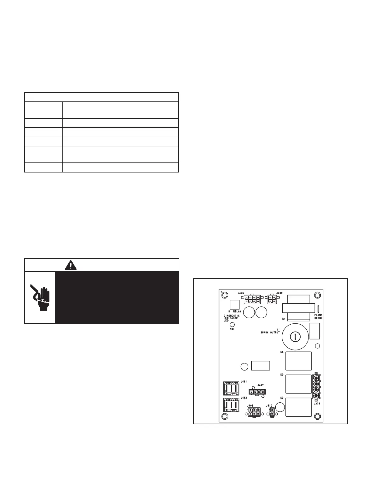
FIGURE 14

 Loading...

