Page 26
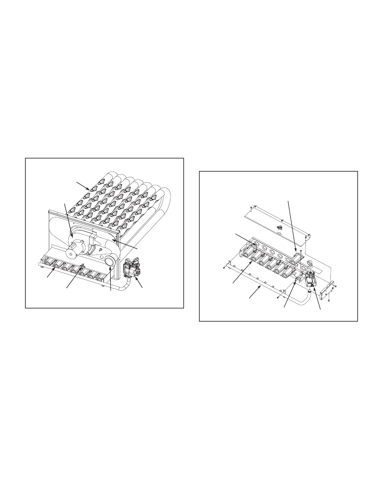
3-Heat Exchanger Figure 15
The LGM units use aluminized steel inshot burners with
tubular aluminized (stainless is optional) steel heat ex-
changers and redundant gas valve. Burners in all units
use a burner venturi to mix gas and air for proper com-
bustion. Combustion takes place at each tube entrance.
As hot combustion gases are drawn upward through each
tube by the combustion air inducer, exhaust gases are
drawn out the top and fresh air/gas mixture is drawn in
at the bottom. Heat is transferred to the air stream from
all surfaces of the heat exchanger tubes. The supply air
blower forces air across the tubes to extract the heat of
combustion. The shape of the tubes ensures maximum
heat exchange.
The gas valves on two stage units accomplish staging by
allowing more or less gas to the burners as called for by
heating demand.
HEAT EXCHANGER ASSEMBLY
BURNER
COMBUSTION
AIR INDUCER
VENT
CONNECTOR
GAS VALVE
HEAT
EXCHANGER
TUBE
ROLLOUT
SWITCH
FLUE BOX
COVER
FIGURE 15
4-Burner Box Assembly Figure 16
sensing electrode and gas valve. Ignition board A3 and
A12 control all functions of the assembly.
Burners
All units use inshot burners. Burners are factory set and
do not require adjustment. A peep hole with cover is fur-
-
ways operate the unit with the access panel in place.
Burners can be removed individually for service on older
units. On newer units, burners are connected and the en-
tire assembly can be removed. Burner maintenance and
service is detailed in the SERVICE CHECKS section of
Orice
-
from the burners.
NOTE - Do not use thread sealing compound on the oric-
es. Using thread sealing compound may plug the orices.
BURNER BOX ASSEMBLY
GAS VALVE
GAS MANIFOLD
FLAME
SENSOR
BURNERS
IGNITOR
REMOVE INDIVIDUAL BURNERS ON
OLDER UNITS; REMOVE THE ENTIRE
BURNER ASSEMBLY ON NEWER UNITS.
FIGURE 16
 Loading...


