EasyManuals Logo

Lennox MLA Series User Manual

Lennox MLA Series
20 pages
To Next Page IconTo Next Page
To Previous Page IconTo Previous Page
Page #15 background imageLoading...
Page #15 background image
15
Table 7. Single Zone Installation Wiring Requirements
System and Terminal
Designations
System Capacity System Voltage
Number of
Conductors
Wire Type Wire Gauge / MCA
Indoor to Outdoor
Wiring
(Communication/
Power)
1, 2, 3 and GND
12K 208/230VAC 4
Stranded and
unshielded
16AWG
Outdoor to Main Power
L1, L2 and GND
12K 208/230VAC 3
Stranded and
unshielded
16AWG / 9A
1
1
ON
ON
1
1
ON
ON
Mode
Mode
INACTIVE
INACTIVE
Factory
Setting
Factory
Setting
For Setting Auto-Restart
SW1
SW1
ACTIVE
ACTIVE
1
1
ON
ON
1
1
ON
ON
Mode
Mode
INACTIVE
INACTIVE
Factory
Setting
Factory
Setting
For Setting Down louver
SW101
SW101
ACTIVE
ACTIVE
1
1
2
2
ON
ON
1
1
2
2
ON
ON
1
1
2
2
ON
ON
1
1
2
2
ON
ON
SW103
SW103
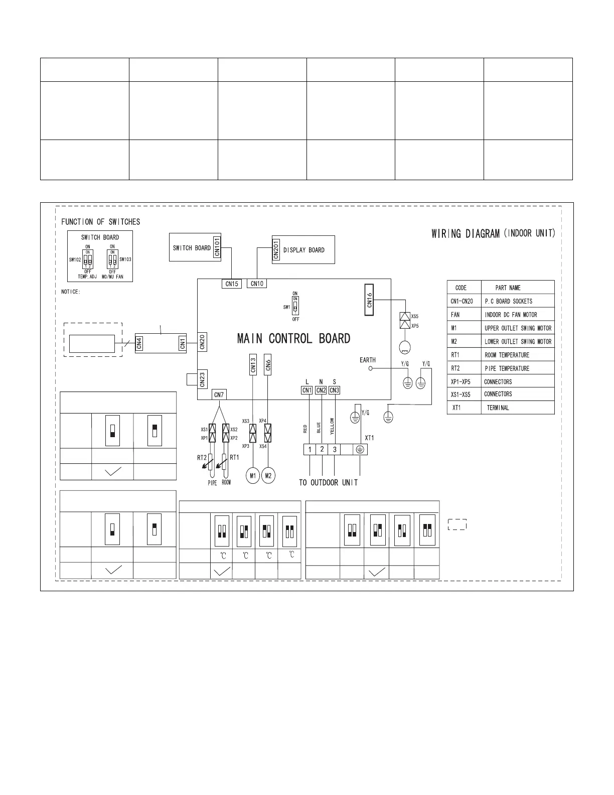
For Setting Fan Motor Control then No Power Request
FAN OFF
LOW
FAN SPEED
SETTING
FAN SPEED
TERMAL
Factory
Setting
Factory
Setting
Mode
Mode
1
1
2
2
ON
ON
1
1
2
2
ON
ON
1
1
2
2
ON
ON
1
1
2
2
ON
ON
SW102
SW102
For temp. Compensation
0
2
4
-2
Mode
Mode
Factory
Setting
Factory
Setting
M
FAN
Adapter
board
Programmable
Wi red Controller
This symbol indicates the
element is optional,the actual
shape shall prevail.
4
Optional
THIS UNIT SUPPORTS THE
PROGRAMMABLE WIRED CONTROL ONLY.
FACTORY INSTALLED
Figure 22. MFMA012-S4-2P Unit Wiring Diagram

Questions and Answers:

Question and Answer IconNeed help?

Do you have a question about the Lennox MLA Series and is the answer not in the manual?

Lennox MLA Series Specifications

General IconGeneral
BrandLennox
ModelMLA Series
CategoryAir Conditioner
LanguageEnglish

Related product manuals