112
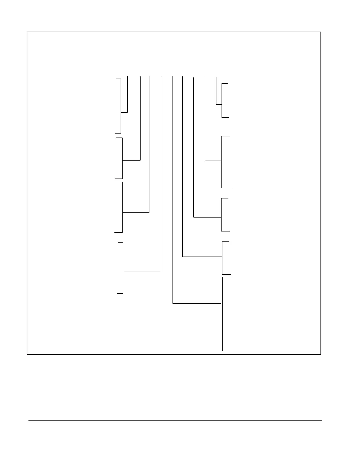
25.3. Configuration ID 2
CONFIGURATION ID 2
Not Installed = N
Installed on M3 = C
Installed on DDC
Controller = D
Dirty Filter Switch (S27) [2]
Not Installed = N
Installed on M3 = C
Installed on DDC Controller = D
Not Installed = N
Installed on DI-2 = 2
Installed on DI-3 = 3
[5] Phase / Voltage
Detection*
N = Not Installed
1 = Enabled Internal (Lennox)
2 = External (A42) Phase Detection
on DI-2
3 = External (A42) Phase Detection
on DI-3
N = Not Installed
Y = Installed
[8] Load Shedding
N = Not Installed
G = Global (P297 - pin 9)
2 = Installed on DI-2
3 = Installed on DI-3
[9] Electric Heat
[1]
Air Flow Proving
Switch (S52)
[3]
Overflow Switch
(S149 / S179)
[4]
Motor Overload
Switch (S42)
Not Installed = N
Installed on DI-2 = 2
Installed on DI-3 = 3
[7] Zone Bypass Damper
N = Not Installed
Y = Installed
[6] Ultra Violet Lamp
N = Not Installed
Y = Installed
* When Phase / Voltage detection monitoring is enabled on three-phase system and
configured incorrectly will cause the system to go to demand hold and restart after
3 minutes.
IMPORTANT: Always refer to the white sticker titled ORIGINAL FACTORY UNIT CONFIGURATION located inside the control box area.
1 2 3 4 5 6 7 8 9
Figure 36. Configuration ID 2