Page 31
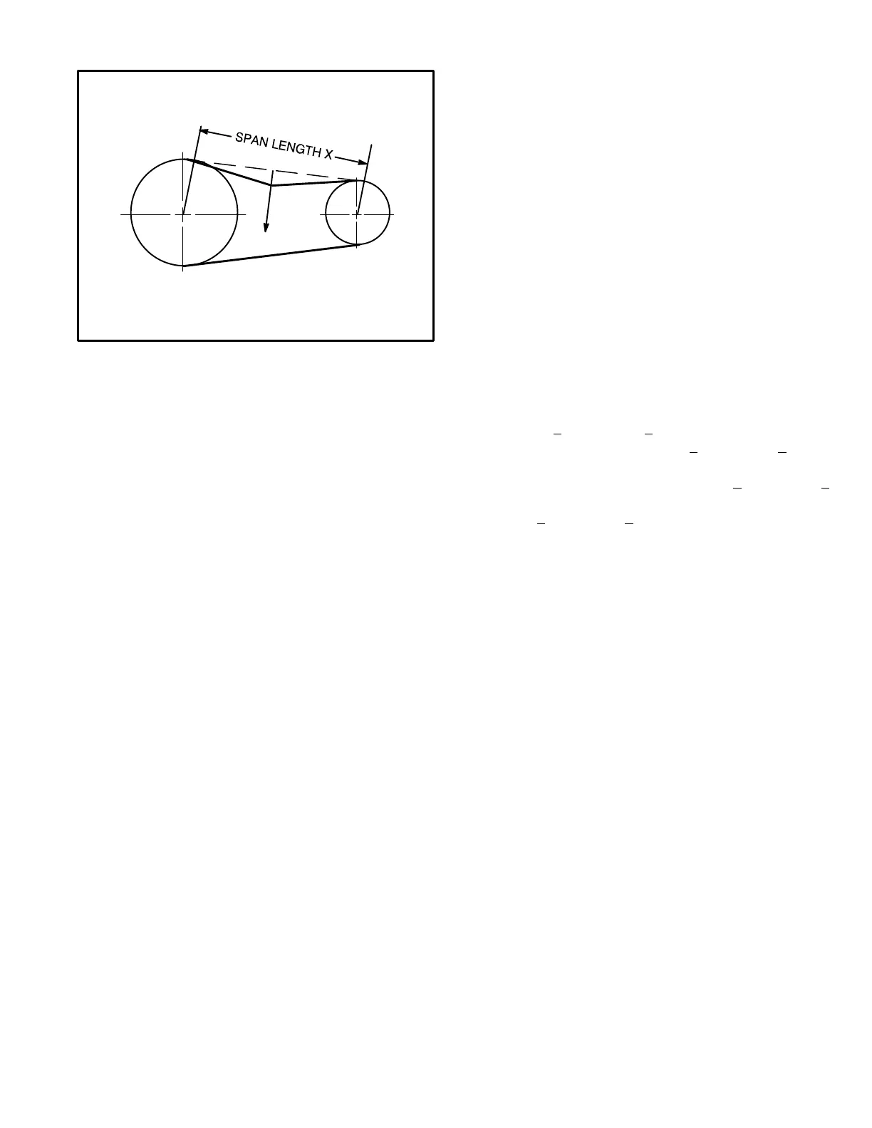
1− Measure span length X. See figure 15.
MEASURE BELT TENSION
FIGURE 15
DEFLECTION 1/64" PER INCH OF SPAN
OR 1.5MM PER 100MM OF SPAN
FORCE
2− Apply perpendicular force to center of span (X) with
enough pressure to deflect belt 1/64" for every inch of
span length or 1.5mm per 100mm of span length.
Example: Deflection distance of a 40" span would be
40/64" or 5/8".
Example: Deflection distance of a 400mm span would
be 6mm.
3− Measure belt deflection force. The deflection force
should be 7.0 lbs.
A force below these values indicates an underten-
sioned belt. A force above these values indicates an
overtensioned belt.
D−Optional Electric Heat Components
EHA parts arrangement is shown in figures 16 through 19.
All electric heat sections consist of electric heating ele-
ments exposed directly to the air stream. See figure 1 for
SCA120 units. Two electric heat sections (first section and
second section) are used in all 30kW through 90kW heat-
ers used in SCA240/SCB288 units. Multiple-stage ele-
ments are sequenced on and off in response to thermostat
demand.
1−Main Control Box Components
A55, A60, K9, T2, and F4
The main control box houses a few of the electric heat
controls, such as: the main control module A55, second
electric heat section control panel A60, electric heat con-
trol hat section for 45 - 90 kW (electric heat relay K9
and transformer T2), and unit fuse block F4. For a
description of the components see section I-A.
2−Contactors K15, K16, K17 and K18
Contactors K15, K16, K17 and K18 are all three-pole
double-break contactors located on the electric heat
vestibule. K15 and K16 are located on the first electric
heat section, while K17 and K18 are located on the sec-
ond electric heat section. However, in the 15 and 30kW
heaters, the first section houses all contactors and
fuses. All contactors are equipped with a 24VAC coil.
The coils in the K15 and K16 contactors are ener-
gized by the main panel A55, while the coil in the K17
and K18 contactors are energized by the electric
heat 2 control panel A60. Contactors K15 and K17
energize the first stage heating elements, while K16 and
K18 energize the second stage heating elements.
3−High Temperature Limits S15 and S107 (Primary)
S15 and S107 are SPST N.C. auto-reset thermostats lo-
cated on the back panel of the electric heat section below
the heating elements. S15 is the high temperature limit for
the first electric heat section, while S107 is the high tem-
perature limit for the second electric heat section. Both
thermostats are identical and are wired in series with the
first stage contactor coil. When either S15 or S107 opens,
indicating a problem in the system, contactor K15 is de-
energized. When K15 is de-energized, first stage and all
subsequent stages of heat are de-energized. The thermo-
stats used on EHA360-45-1 Y/G/J are factory set to open
at 200_F + 5_F (93.3_C + 2.8_C) on a temperature rise
and automatically reset at 160_F + 6_F (71.1_C + 3.3_C)
on a temperature fall. All other electric heat section ther-
mostats are factory set to open at 170_F + 5_F (76.7_C +
2.8_C) on a temperature rise and automatically reset at
130_F + 6_F (54.4_C + 3.3_C) on a temperature fall. The
thermostats are not adjustable.
4−Terminal Strip TB3
Electric heat line voltage connections are made to termi-
nal strip TB3 (or a fuse block on some models) located in
the upper left corner of the electric heat vestibule.
5−Heating Elements HE1 through HE14
Heating elements are composed of helix wound bare
nichrome wire exposed directly to the air stream. Three
elements are connected in a three-phase arrange-
ment. The elements in 208/230V units are connected
in a Delta" arrangement. Elements in 460 and 575V
units are connected in Wye" arrangement. Each stage
is energized independently by the corresponding con-
tactors located on the electric heat vestibule panel.
Once energized, heat transfer is instantaneous. High
temperature protection is provided by primary and re-
dundant high temperature limits and overcurrent
protection is provided by fuses.
6−Fuse F3
Fuse F3 are housed in a fuse block which holds three
fuses. Each F3 fuse is connected in series with each leg of
electric heat. Figures 17 and 18 and tables 4 and 3 show
the fuses used with each electric heat section. For
simplicity, the service manual labels the fuses F3 − 1
through F3 − 8.

 Loading...


