19
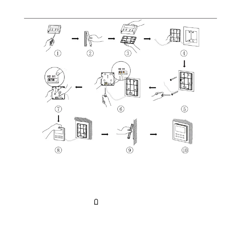
Fig. 5.8 Installation diagram for wired controller
Fig. 5.8 is the simple installation process of wired controller; please pay
attention to the following items:
(1) Before installation, please cut off the power for indoor unit.
(2) Pull out the two-core twisted pair from the installation hole on wall, and then
pull this wire through the " ” shape hole at the rear side of Soleplate of wired
controller.
Wired Controller VEWCL1B

 Loading...


